

Question: Figure 4 . 3 . 6 Pipe system for example 4 . 3 . 5 . ? ? h L m = h L e
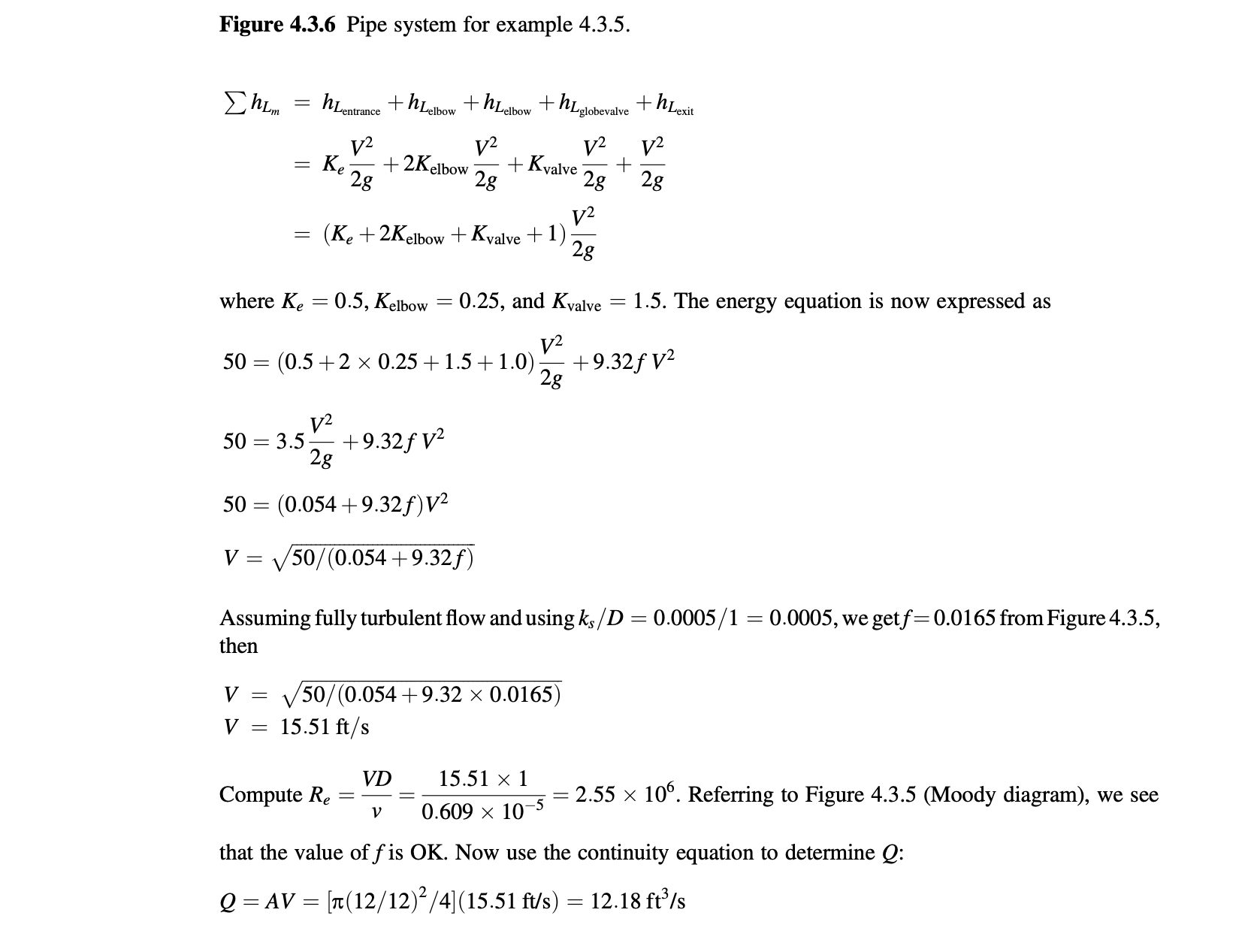
Figure Pipe system for example
where and The energy equation is now expressed as
Assuming fully turbulent flow and using we get from Figure then
Compute Referring to Figure Moody diagram we see that the value of is Now use the continuity equation to determine :
Step by Step Solution
There are 3 Steps involved in it
1 Expert Approved Answer
Step: 1 Unlock

Question Has Been Solved by an Expert!
Get step-by-step solutions from verified subject matter experts
Step: 2 Unlock
Step: 3 Unlock