

Question: Figure 4.38(a) shows a discrete common-source MOSFET amplifier utilizing the drain-to-gate feedback biasing arrangement. The input signal is coupled to the gate via a
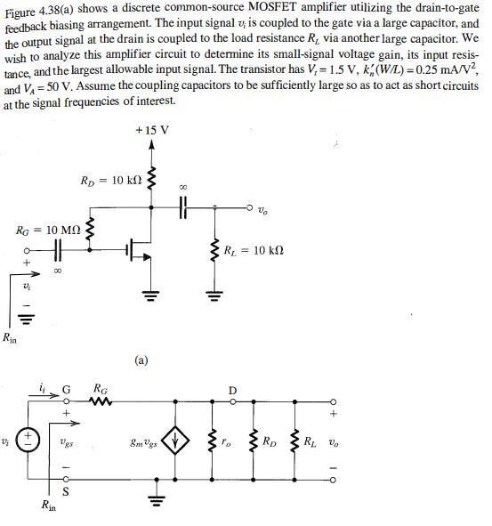
Figure 4.38(a) shows a discrete common-source MOSFET amplifier utilizing the drain-to-gate feedback biasing arrangement. The input signal is coupled to the gate via a large capacitor, and the output signal at the drain is coupled to the load resistance R, via another large capacitor. We wish to analyze this amplifier circuit to determine its small-signal voltage gain, its input resis- tance, and the largest allowable input signal. The transistor has V, = 1.5 V, k (WL) = 0.25 mA/V?, and V = 50 V. Assume the coupling capacitors to be sufficiently large so as to act as short circuits at the signal frequencies of interest. + 15 V Rp = 10 kN RG = = 10 MN R = 10 k Ria (a) RG D Vgs 8m Vgs Rp S
Step by Step Solution
3.46 Rating (162 Votes )
There are 3 Steps involved in it
To analyze this discrete commonsource MOSFET amplifier we aim to find 1 Smallsignal voltage gain Av ... View full answer

Get step-by-step solutions from verified subject matter experts