

Question: FIGURE 6 2 0 6 . 7 . Iigure 6 . 2 0 show's the one - line diagram of a simple three - bus
FIGURE
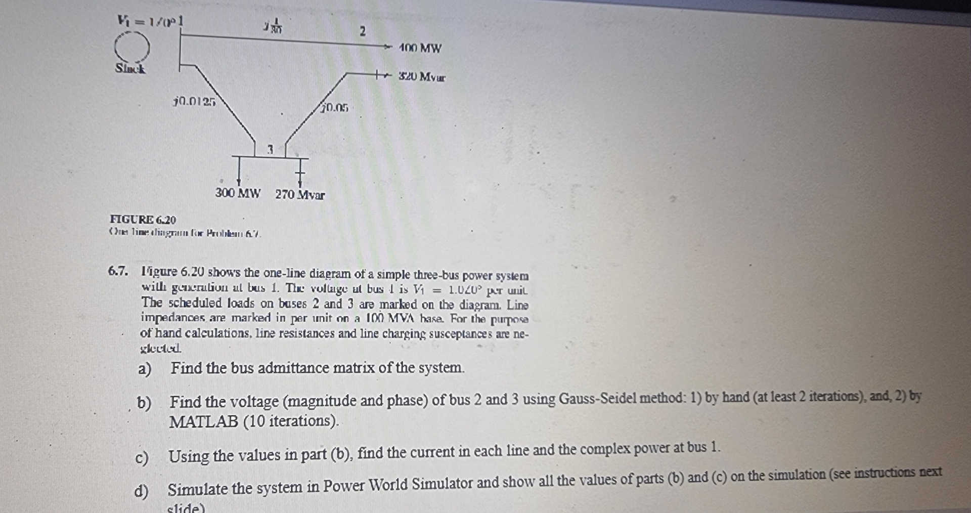
Iigure show's the oneline diagram of a simple threebus power system will gencration al bus The vollage at bus is pre unil The scheduled loads on buses and are marked on the diagram. Line impedances are marked in per unit on a IOI MVA hase. For the purpose of hand calculations, line resistances and line charging susceptances are neslecterl.
a Find the bus admittance matrix of the system.
b Find the voltage magnitude and phase of bus and using GaussSeidel method: by hand at least iterations and, by MATLAB iterations
c Using the values in part b find the current in each line and the complex power at bus
d Simulate the system in Power World Simulator and show all the values of parts b and c on the simulation see instructions ne
Step by Step Solution
There are 3 Steps involved in it
1 Expert Approved Answer
Step: 1 Unlock

Question Has Been Solved by an Expert!
Get step-by-step solutions from verified subject matter experts
Step: 2 Unlock
Step: 3 Unlock