

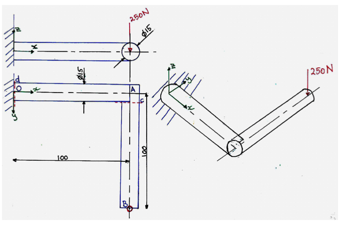
Question: Figure 7 : Elbow beam with vertical load at tip ( i ) The line marked d is a plane parallel to the wall where
Figure : Elbow beam with vertical load at tip
i The line marked is a plane parallel to the wall where the beam enters the wall. Section the
beam OD at plane Draw a Free Body Diagram showing the internal shear forces and moments
on this face. You should draw the portion of beam which contains the external force of N
ii On the plane calculate the different stresses on the face. Make a neat sketch showing the
distribution of the various stresses, including the directions.
iii Consider the magnitude of the shear stresses due to applied shear forces, compared to shear
stresses arising due to applied torque. Which of these is most meaningful in sizing the beam?
Could you demonstrate this analytically for a beam of circular section?
iv Identify the points on plane where the beam is most highly stressed. At this point, find the
maximum and minimum principal stresses, as well as the maximum shear stress. You may use a
graphical version of Mohr's circle or the analytical equations.
v Assume this beam is made from low carbon steel AISI which has an elastic modulus
GPa, yield strength MPa and Ultimate Tensile Strength MPa.
Using the Maximum Shear Stress Theory of Failure for permanent deformation, what is the
factor of safey at this location?
Qvi: MPa;MPa
Qvii; Factor of safety on yield ~~
Please solve asap, answering every question step by step with expalnations and diagrams
Step by Step Solution
There are 3 Steps involved in it
1 Expert Approved Answer
Step: 1 Unlock

Question Has Been Solved by an Expert!
Get step-by-step solutions from verified subject matter experts
Step: 2 Unlock
Step: 3 Unlock