

Question: ( Figure 7 ) is a conceptual description of Stack. When a push operation is performed, data enters the array, and when a pop operation
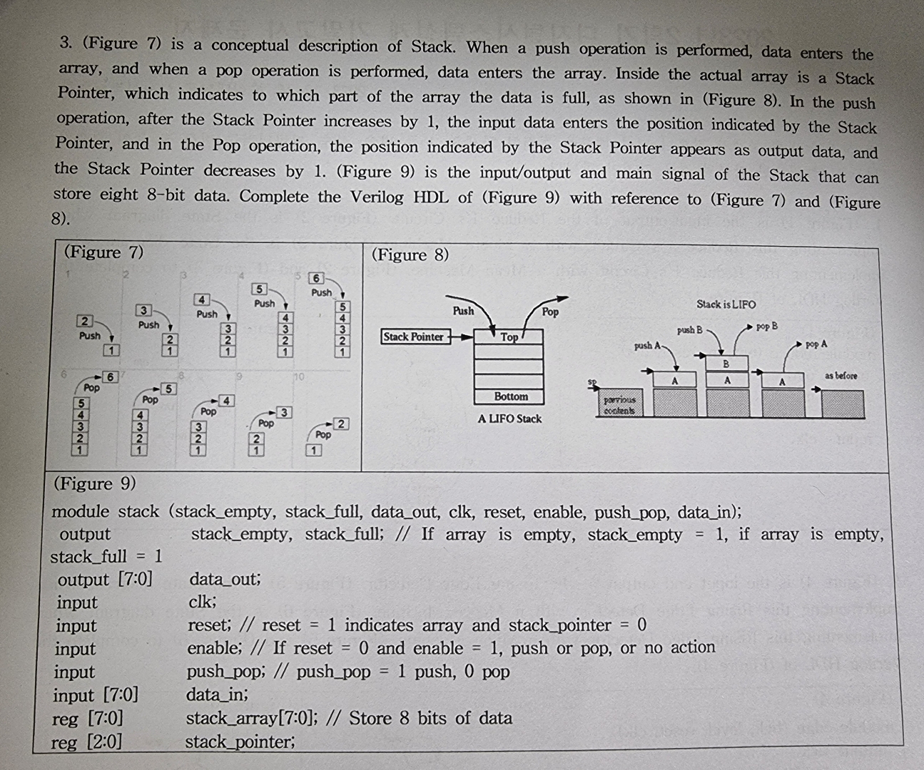
Figure is a conceptual description of Stack. When a push operation is performed, data enters the array, and when a pop operation is performed, data enters the array. Inside the actual array is a Stack Pointer, which indicates to which part of the array the data is full, as shown in Figure In the push operation, after the Stack Pointer increases by the input data enters the position indicated by the Stack Pointer, and in the Pop operation, the position indicated by the Stack Pointer appears as output data, and the Stack Pointer decreases by Figure is the inputoutput and main signal of the Stack that can store eight bit data. Complete the Verilog HDL of Figure with reference to Figure and Figure
Figure y
module stack stackempty, stackfull, dataout, clk reset, enable, pushpop, datain; output stackempty, stackfull; If array is empty, stackempty if array is empty, stackfull output : dataout; input clk;
input reset; reset indicates array and stackpointer
input enable; If reset and enable push or pop, or no action
input pushpop; pushpop push, pop
input : datain;
reg : stackarray:; Store bits of data
reg : stackpointer;
Step by Step Solution
There are 3 Steps involved in it
1 Expert Approved Answer
Step: 1 Unlock

Question Has Been Solved by an Expert!
Get step-by-step solutions from verified subject matter experts
Step: 2 Unlock
Step: 3 Unlock