

Question: Figure B2a shows an LCR circuit, the component values are R1= 402, L1= 0.5 H and C1=C2=10 F. The supply being 120 Vrms at
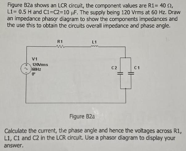
Figure B2a shows an LCR circuit, the component values are R1= 402, L1= 0.5 H and C1=C2=10 F. The supply being 120 Vrms at 60 Hz. Draw an impedance phasor diagram to show the components impedances and the use this to obtain the circuits overall impedance and phase angle. V1 120Vims 60Hz 0 R1 ww L1 C2 23 HH C1 Figure B2a Calculate the current, the phase angle and hence the voltages across R1, L1, C1 and C2 in the LCR circuit. Use a phasor diagram to display your answer.
Step by Step Solution
★★★★★
3.56 Rating (163 Votes )
There are 3 Steps involved in it
1 Expert Approved Answer
Step: 1 Unlock

Question Has Been Solved by an Expert!
Get step-by-step solutions from verified subject matter experts
Step: 2 Unlock
Step: 3 Unlock