

Question: FIGURE P - 1 9 - 9 Map for sewer layout. Elevations are in meters above mean sea level at points noted by dots. These
FIGURE P
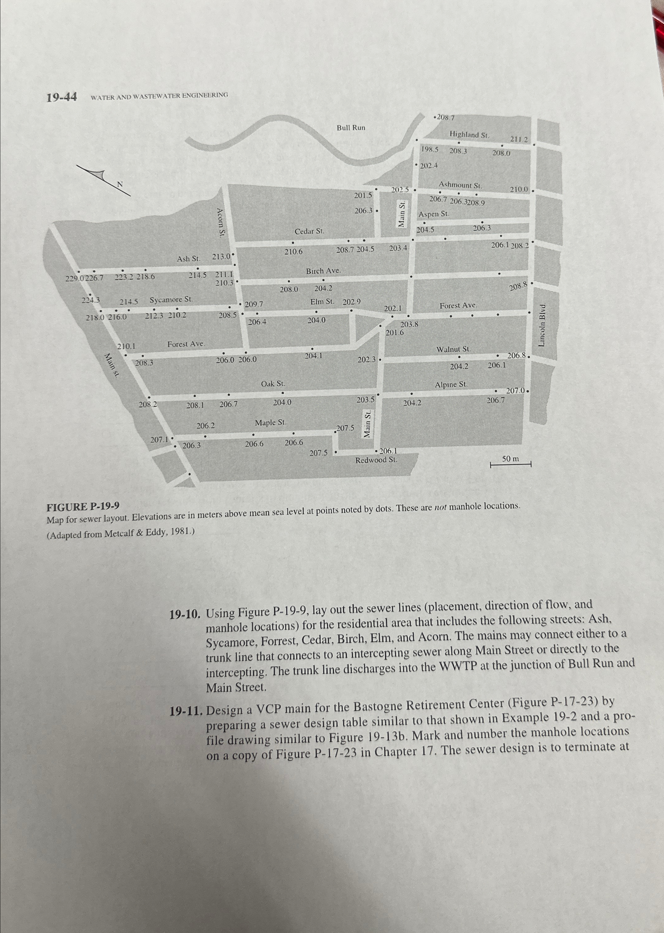
Map for sewer layout. Elevations are in meters above mean sea level at points noted by dots. These are not manhole locations.
Adapted from Metcalf & Eddy,
Using Figure P lay out the sewer lines placement direction of flow, and manhole locations for the residential area that includes the following streets: Ash, Sycamore, Forrest, Cedar, Birch, Elm, and Acorn. The mains may connect either to a trunk line that connects to an intercepting sewer along Main Street or directly to the intercepting. The trunk line discharges into the WWTP at the junction of Bull Run and Main Street.
Design a VCP main for the Bastogne Retirement Center Figure P by preparing a sewer design table similar to that shown in Example and a profile drawing similar to Figure b Mark and number the manhole locations on a copy of Figure P in Chapter The sewer design is to terminate at
Step by Step Solution
There are 3 Steps involved in it
1 Expert Approved Answer
Step: 1 Unlock

Question Has Been Solved by an Expert!
Get step-by-step solutions from verified subject matter experts
Step: 2 Unlock
Step: 3 Unlock