

Question: Figure Q.4(c) shows a Schmitt Trigger circuit. Assuming that the output will saturate at V sat = 12 V and V i = 8 sin
Figure Q.4(c) shows a Schmitt Trigger circuit. Assuming that the output will saturate at ±Vsat = ±12 V and Vi = 8 sin wt [V],
(i) Derive the expression for VUTP and VLTP.
(ii) Draw and label the output signal, Vo.
(iii) Draw and label the transfer characteristic, Vo vs Vi.
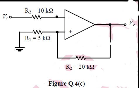
R2 = 10 k2 ww V Vo R1 = 5 kQ R2 = 20 k2 Figure Q.4(c)
Step by Step Solution
★★★★★
3.32 Rating (146 Votes )
There are 3 Steps involved in it
1 Expert Approved Answer
Step: 1 Unlock

Question Has Been Solved by an Expert!
Get step-by-step solutions from verified subject matter experts
Step: 2 Unlock
Step: 3 Unlock
Document Format (2 attachments)
6365a846da9c7_231147.pdf
180 KBs PDF File
6365a846da9c7_231147.docx
120 KBs Word File