

Question: Finite State Machine Diagram and Creating Schematic Design Please show all the steps of the question and explanations would be very helpful! I really want
Finite State Machine Diagram and Creating Schematic Design
Please show all the steps of the question and explanations would be very helpful! I really want to understand the material.
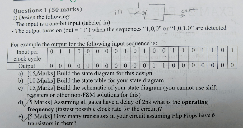
Questions 1 (50 marks) 1) Design the following: - The input is a one-bit input (labeled in). The output turns on (out -"1") when the sequences "1 ,0,0" or "1,0,1,0" are detected For example the output for the following input sequence is: Input per 0 1 000 1 0010 1 11 clock cycle Output 0 0 0 0 0 0 1 0 0 00 0 a) [15,Marks] Build the state diagram for this design. b) [10 Marks] Build the state table for your state diagram. c) [15 Marks] Build the schematic of your state diagram (you cannot use shift registers or other non-FSM solutions for this) frequency (fastest possible clock rate for the circuit)? transistors in them? d) 15 Marks] Assuming all gates have a delay of 2ns what is the operating e) 5 Marks] How many transistors in your circuit assuming Flip Flops have Questions 1 (50 marks) 1) Design the following: - The input is a one-bit input (labeled in). The output turns on (out -"1") when the sequences "1 ,0,0" or "1,0,1,0" are detected For example the output for the following input sequence is: Input per 0 1 000 1 0010 1 11 clock cycle Output 0 0 0 0 0 0 1 0 0 00 0 a) [15,Marks] Build the state diagram for this design. b) [10 Marks] Build the state table for your state diagram. c) [15 Marks] Build the schematic of your state diagram (you cannot use shift registers or other non-FSM solutions for this) frequency (fastest possible clock rate for the circuit)? transistors in them? d) 15 Marks] Assuming all gates have a delay of 2ns what is the operating e) 5 Marks] How many transistors in your circuit assuming Flip Flops have
Step by Step Solution
There are 3 Steps involved in it

Get step-by-step solutions from verified subject matter experts