

Question: FIRST ACTIVITY: DESIGN OF A SMALL MICROPROCESSOR (70/100) DESIGN PROBLEM Implement the following 4-bit microprocessor: SWITCHES LEDS IN OUT 0 BUS R1 RO A B
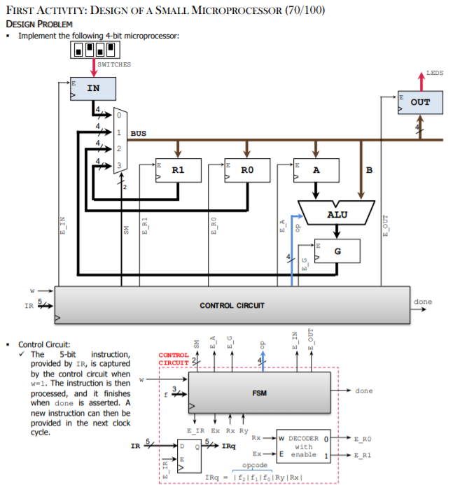
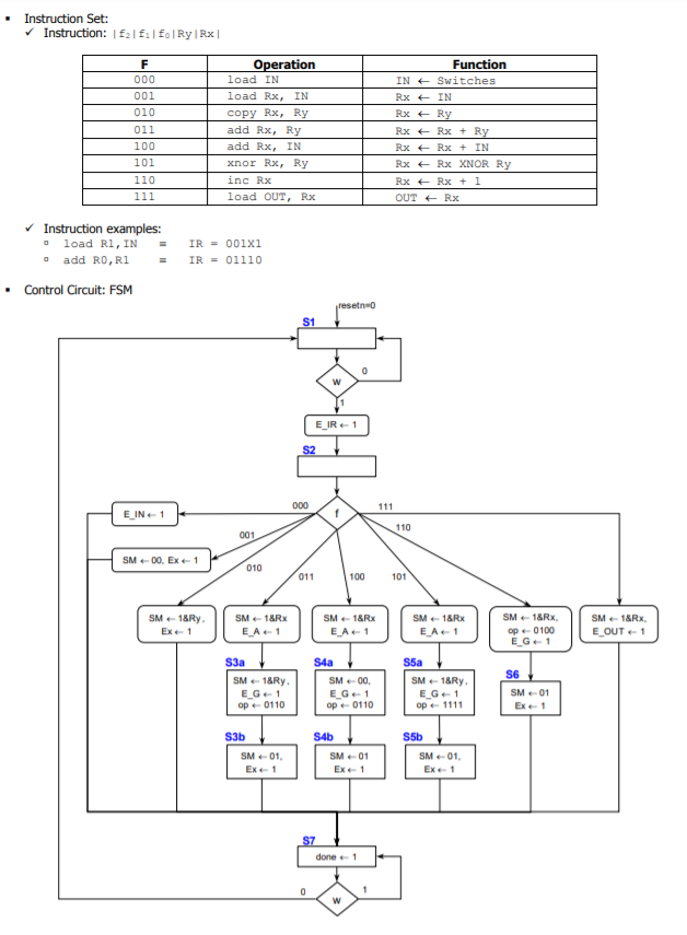
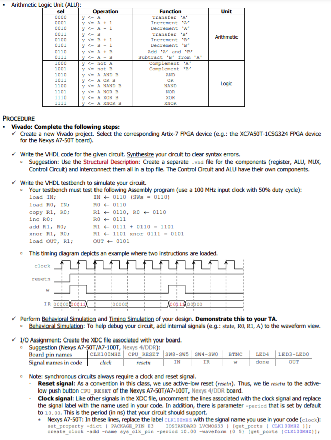
FIRST ACTIVITY: DESIGN OF A SMALL MICROPROCESSOR (70/100) DESIGN PROBLEM Implement the following 4-bit microprocessor: SWITCHES LEDS IN OUT 0 BUS R1 RO A B ALU SM E_R1 E_RO E_OUT G E_G IS done CONTROL CIRCUIT OUT CONTROL CIRCUIT Control Circuit: The 5-bit instruction, provided by IR, is captured by the control circuit when w=1. The instruction is then processed, and it finishes when done is asserted. A new instruction can then be provided in the next clock cycle. FSM done E_RO IR VO ELIR EX RX RY RX-W DECODER O AIR with EXE enable 1 E opode IRq - falf, Ry|RX| ER1 E_IR Instruction Set: Instruction: E2F1 FoRy | Rx F 000 001 010 011 100 101 110 111 Operation load IN load Rx, IN copy Rx, Ry add Rx, Ry add Rx, IN xnor Rx, Ry inc Rx load OUT, Rx Function IN + Switches Rx + IN Rx + Ry Rx+ Rx + Ry Rx+ Rx + IN Rx+ Rx XNOR Ry RxRx + 1 OUT + Rx a Instruction examples: load RI, IN add RO, R1 Control Circuit: FSM IR = 001x1 IR = 01110 . reset S1 0 w E_IR-1 S2 000 111 E_IN-1 f 110 001 SM-00, EX-1 010 011 100 101 SM-18Ry. Ex1 SM 1&RX E_A1 SM1&RX E_A1 SM=1&Rx EA 1 SM-1&Rx op-0100 EG 1 SM 1&RX, E_OUT 1 S4a S6 S3a SM 18Ry E_G1 op 0110 SM-00 E_G1 op 0110 S5a SM-18Ry, E_G1 op 1111 SM-01 Ex-1 S3b SM01, Ex 1 S4b SM 01 Ex1 S5b SM-01. Ex-1 S7 done1 0 1 w Unit Arithmetic Arithmetic Logic Unit (ALU): sel Operation 0000 0001 y
Step by Step Solution
There are 3 Steps involved in it

Get step-by-step solutions from verified subject matter experts