

Question: Recalculate the turn on loss of the MOSFET. How does it compare to the value obtained in step 6? Change gate resistor to 1002
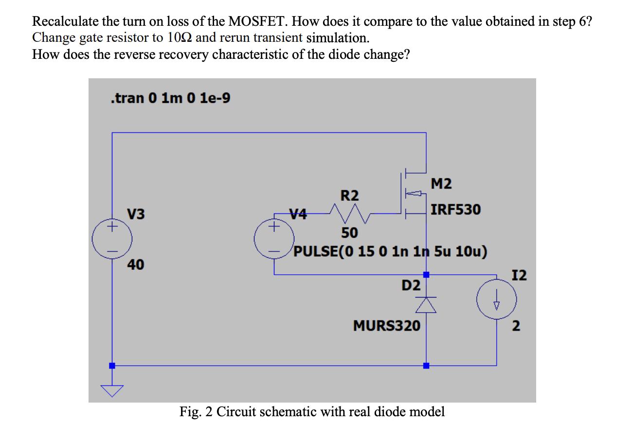
Recalculate the turn on loss of the MOSFET. How does it compare to the value obtained in step 6? Change gate resistor to 1002 and rerun transient simulation. How does the reverse recovery characteristic of the diode change? .tran 0 1m 0 le-9 V3 40 V4 R2 50 PULSE(0 15 0 1n 1n 5u 10u) D2 M2 IRF530 MURS320 Fig. 2 Circuit schematic with real diode model b 12 2
Step by Step Solution
3.41 Rating (148 Votes )
There are 3 Steps involved in it
The circuit schematic in Figure 2 shows a MOSFET M2 and a diode D2 associated in a typical source setup The MOSFET is driven by a heartbeat generator V3 with a 15 V plentifulness 1 nS rise time and 5 ... View full answer

Get step-by-step solutions from verified subject matter experts