

Question: FLANGE # 1 1 0 2 PROJECT 4 . 1 2 DIRECTIONS: Download the Imperial Prototype drawing file located in the Prototype Drawing Files folder
FLANGE #
PROJECT
DIRECTIONS:
Download the Imperial
Prototype drawing file located
in the Prototype Drawing Files
folder associated with this book.
Use SAVE AS to save the drawing to your Home directory and rename the drawing Flange
Activate the MODEL tab in the lowerleft corner of the graphics window if it is not already highlighted by left
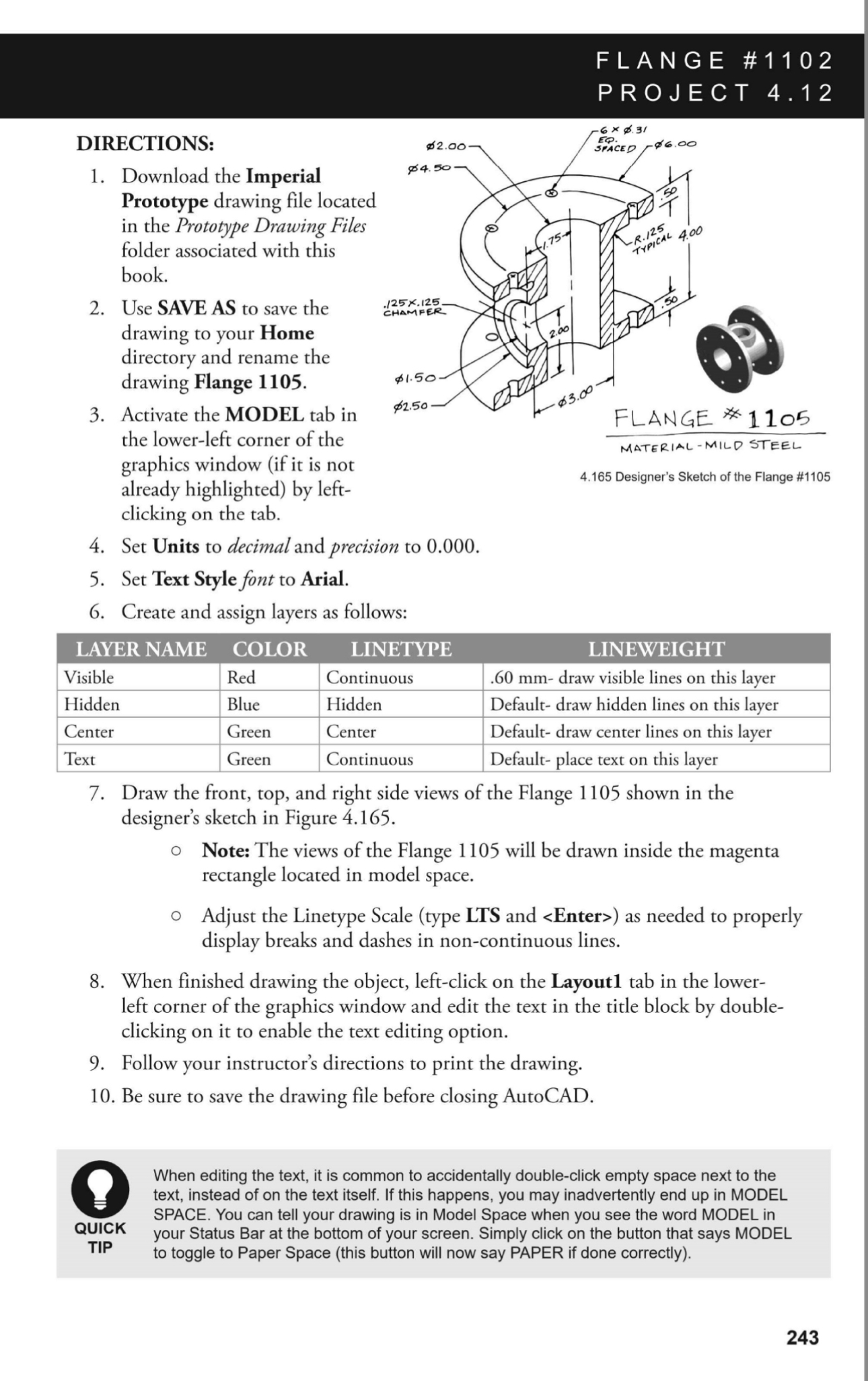
Designer's Sketch of the Flange #
clicking on the tab.
Set Units to decimal and precision to
Set Text Style font to Arial.
Create and assign layers as follows:
tableLAYER NAME,COLOR,LINETYPEVisibleRed,Continuous, mm draw visible lines on this layer,HiddenBlue,Hidden,Default draw hidden lines on this layer,CenterGreen,Center,Default draw center lines on this layer,TextGreen,Continuous,Default place text on this layer,
Draw the front, top, and right side views of the Flange shown in the designer's sketch in Figure
Note: The views of the Flange will be drawn inside the magenta rectangle located in model space.
Adjust the Linetype Scale type LTS and
Step by Step Solution
There are 3 Steps involved in it
1 Expert Approved Answer
Step: 1 Unlock

Question Has Been Solved by an Expert!
Get step-by-step solutions from verified subject matter experts
Step: 2 Unlock
Step: 3 Unlock