

Question: For Problems 3-11, the solution is given, for each example you must explain how each circuit functions. 3. (15 Pts) Each output (Yes, No, Maybe)
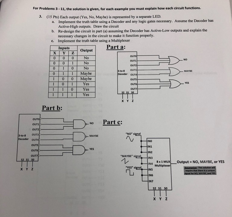
For Problems 3-11, the solution is given, for each example you must explain how each circuit functions. 3. (15 Pts) Each output (Yes, No, Maybe) is represented by a separate LED. Implement the truth table using a Decoder and any logic gates necessary. Assume the Decoder has Active-High outputs. Draw the circuit Re-design the circuit in part (a) assuming the Decoder has Active-Low outputs and explain the necessary changes in the circuit to make it function properly. Implement the truth table using a Multiplexer Inputs a. b. c. Output Part a: No No No NO OUT1 OUT2 -to-8 OUT3 MAYBE 0 10 Maybe Maybe Decoder OUT4 YES Yes 1 1 0Yes Yes OUT X Y Z Part b: OUTO OUT1 OUT2 3-to-8OUT3 Decoder OUT4 No Part c: "NO" signal MAYBE INO YES OUT6 IN2 IN3 N4 Multiplexer OUT7 "MAYBE" signal 8x 1 MUX Output NO, MAYBE, or YES "YES" signalINS X Y Z require that there is a unique IN6 IN7 S2 S1 SO
Step by Step Solution
There are 3 Steps involved in it

Get step-by-step solutions from verified subject matter experts