

Question: For structures consisting of multi - level roofs, snow on the lower roofs often tends to drift toward the upper building structure, such CS Fig.
For structures consisting of multilevel roofs, snow on the lower roofs often tends to drift toward the upper building structure, such CS Fig. Enclosed parking structure with the design snowdrift roof load.
STRATEGY:
Because the beams are equally spaced, the load applied along the length of one beam will be the given roof load multiplied by the
m beam spacing. In other words, this is the portion of the total roof load that acts on one of the beams. CS Fig. shows
the resulting load, along with the support conditions to be assumed for the beam. The magnitude of this distributed load's resultant
is the area under the load curve, and its location is the centroid of the load area. The total load area can be broken up into smaller
areas of simple geometry and used to calculate the magnitude and location of the resultant. This resultant can then be
applied to a freebody diagram of the beam to determine the support reactions. MODELING AND ANALYSIS:
a Equivalent Concentrated Load. Divide the area under the load curve into a rectangle and a triangle CS Fig. and
construct the table below.
The equivalent concentrated load CS Fig. is
Its line of action is located at a distance
the right CS Fig. The load modeled as a triangular and a rectangular area.CS Fig. The load modeled as a triangular and a rectangular area.
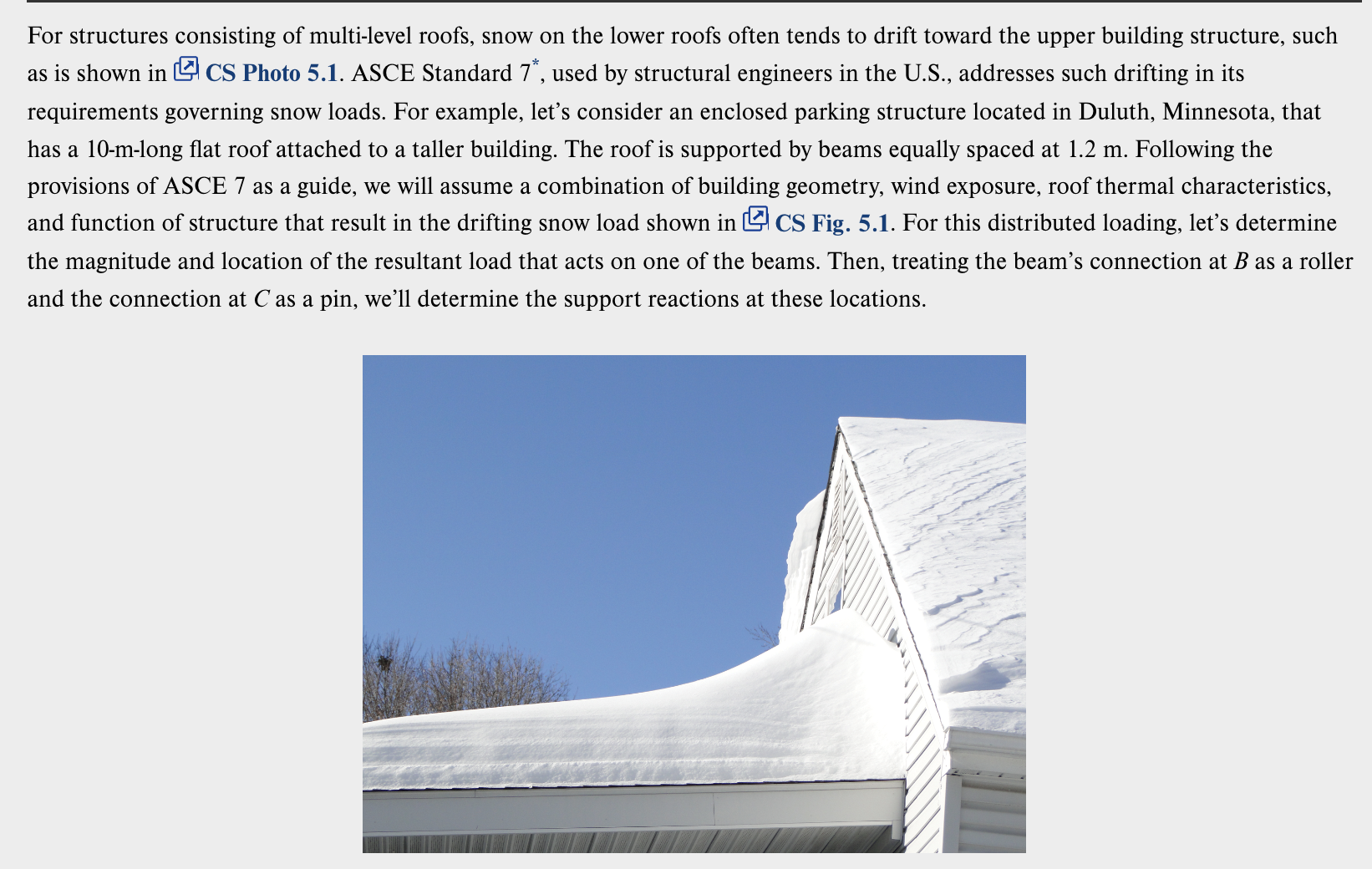
as is shown in CS Photo ASCE Standard used by structural engineers in the US addresses such drifting in its
requirements governing snow loads. For example, let's consider an enclosed parking structure located in Duluth, Minnesota, that
has a mlong flat roof attached to a taller building. The roof is supported by beams equally spaced at Following the
provisions of ASCE as a guide, we will assume a combination of building geometry, wind exposure, roof thermal characteristics,
and function of structure that result in the drifting snow load shown in CS Fig. For this distributed loading, let's determine
the magnitude and location of the resultant load that acts on one of the beams. Then, treating the beam's connection at as a roller
and the connection at as a pin, we'll determine the support reactions at these locations.
Step by Step Solution
There are 3 Steps involved in it
1 Expert Approved Answer
Step: 1 Unlock

Question Has Been Solved by an Expert!
Get step-by-step solutions from verified subject matter experts
Step: 2 Unlock
Step: 3 Unlock