

Question: For the amplifier in the first image, fill the table in image 2. Considering the bases of Q1 & Q2 connected to ground, beta=200(Ic~Ie), VBE=0.7V,
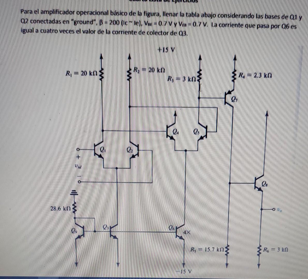

For the amplifier in the first image, fill the table in image 2. Considering the bases of Q1 & Q2 connected to ground, beta=200(Ic~Ie), VBE=0.7V, and VEB=0.7V. The current that passes through Q6 is equal to four times the current value of the collector in Q3.
In the table in the second image, you need to put the voltages of the emitter for each of the transistors indicated in the table.
Please be clear in your answer and show the process. Thank you
Para el amplificador operacional bsico de la figura, llenar la tabla abajo considerando las bases de Q1 y Q2 conectadas en "ground", =200(lcle),VBE=0.7V Y VEB=0.7V. La corriente que pasa por Q6 es \begin{tabular}{|c|c|} \hline \multicolumn{2}{|c|}{ Voltajes de Emisor } \\ \hline Q1 Y Q2 & \\ \hline Q4YQ5 & \\ \hline Q & \\ \hline Q8 & \\ \hline \end{tabular}
Step by Step Solution
There are 3 Steps involved in it

Get step-by-step solutions from verified subject matter experts