

Question: For the circuit shown below in Figure 8 : Figure 8 . Circuit for Problem 7 . ( a ) Find the phasor - domain
For the circuit shown below in Figure :
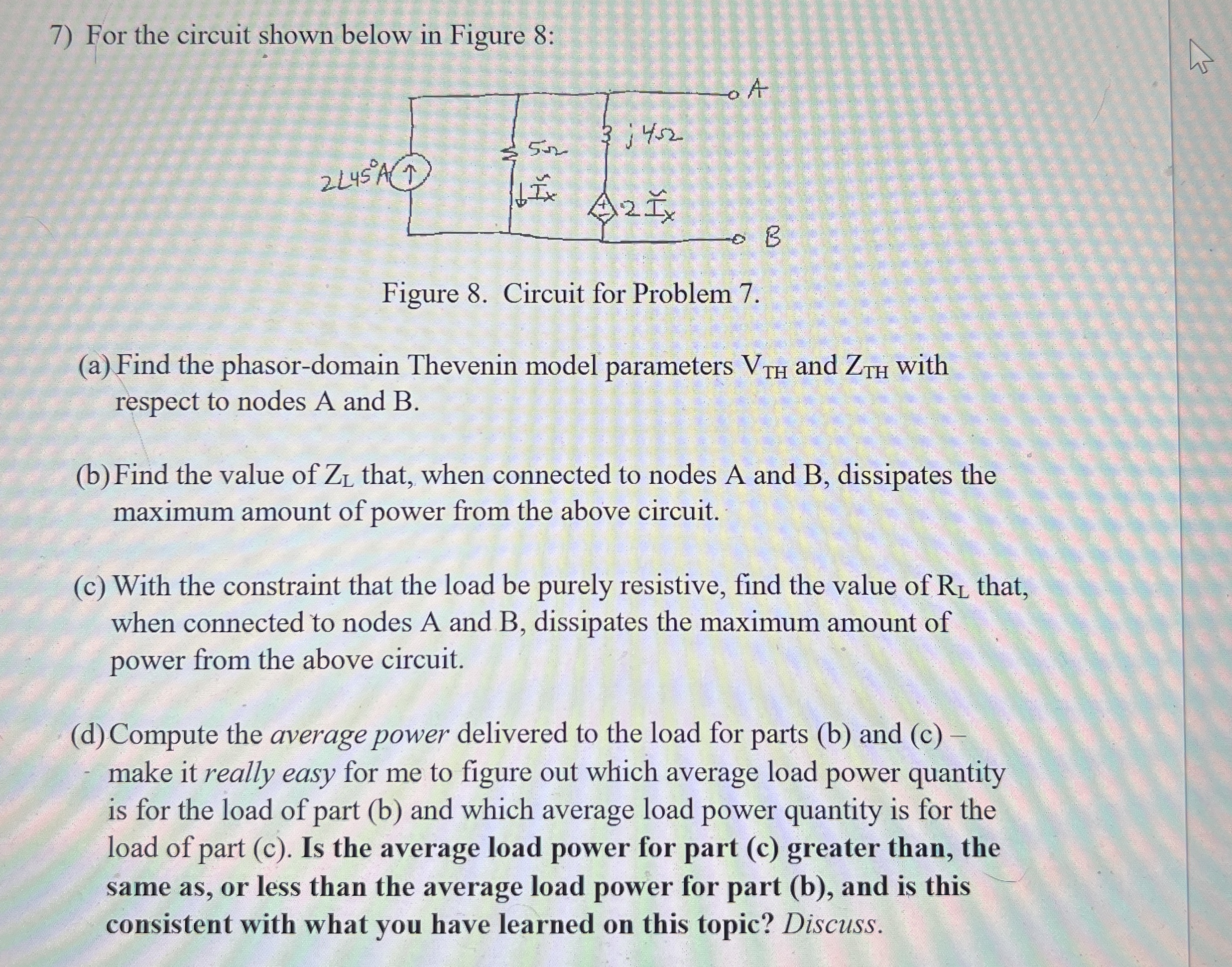
Figure Circuit for Problem
a Find the phasordomain Thevenin model parameters and with respect to nodes A and B
b Find the value of that, when connected to nodes A and B dissipates the maximum amount of power from the above circuit.
c With the constraint that the load be purely resistive, find the value of that, when connected to nodes A and B dissipates the maximum amount of power from the above circuit.
d Compute the average power delivered to the load for parts b and c make it really easy for me to figure out which average load power quantity is for the load of part b and which average load power quantity is for the load of part c Is the average load power for part c greater than, the same as or less than the average load power for part b and is this consistent with what you have learned on this
topic? Discuss POWER ANSWERS SHOULD BE and
Step by Step Solution
There are 3 Steps involved in it
1 Expert Approved Answer
Step: 1 Unlock

Question Has Been Solved by an Expert!
Get step-by-step solutions from verified subject matter experts
Step: 2 Unlock
Step: 3 Unlock