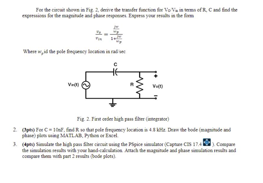
Question: For the circuit shown in Fig. 2, derive the transfer function for Vo/Vin in terms of R. C and find the expressions for the

For the circuit shown in Fig. 2, derive the transfer function for Vo/Vin in terms of R. C and find the expressions for the magnitude and phase responses. Express your results in the form Vo Vin Vin(t) = jw wp jw Wp Where w,id the pole frequency location in rad/sec 1+ Vo(t) Fig. 2. First order high pass filter (integrator) 2. (3pts) For C = 10nF, find R so that pole frequency location is 4.8 kHz. Draw the bode (magnitude and phase) plots using MATLAB, Python or Excel. 3. (4pts) Simulate the high pass filter circuit using the PSpice simulator (Capture CIS 17.4 ). Compare the simulation results with your hand-calculation. Attach the magnitude and phase simulation results and compare them with part 2 results (bode plots).
Step by Step Solution
3.33 Rating (156 Votes )
There are 3 Steps involved in it
Answer 1 Transfer Function VoVin jwRC1jwRC Pole Frequency Location w 1RC 2 For C 10nF t... View full answer

Get step-by-step solutions from verified subject matter experts


