

Question: For the circuit shown in Figure 1 , select R 1 = 1 2 0 k , R 2 = 4 7 k , R
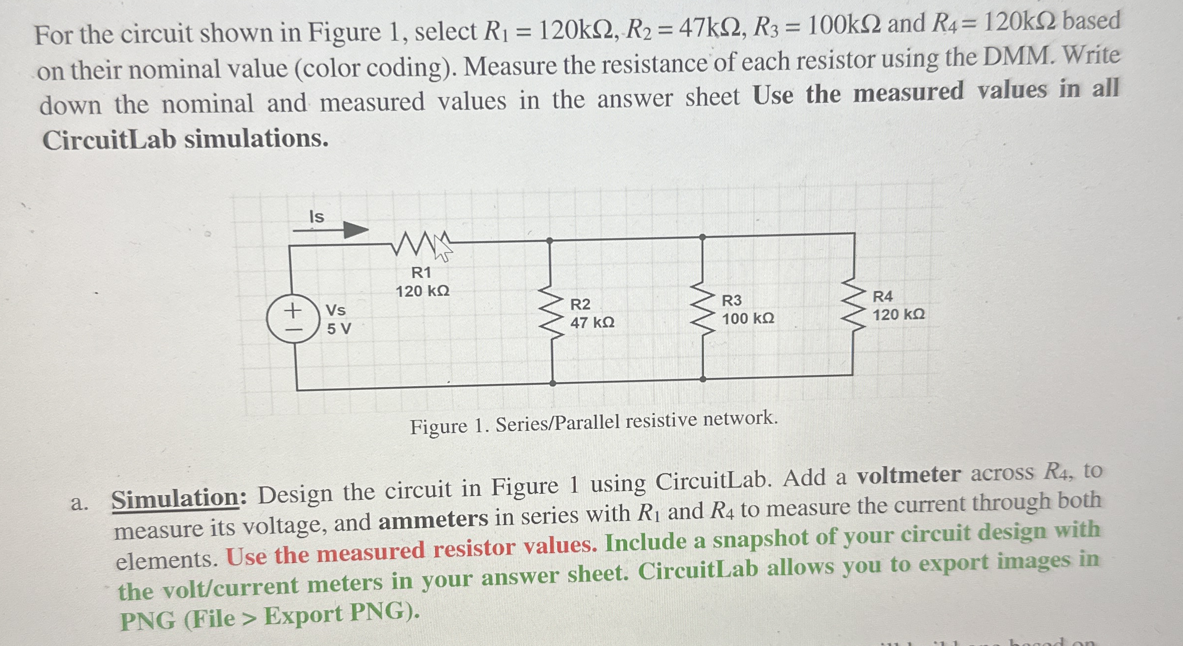
For the circuit shown in Figure select and based on their nominal value color coding Measure the resistance of each resistor using the DMM Write down the nominal and measured values in the answer sheet Use the measured values in all CircuitLab simulations.
Figure SeriesParallel resistive network.
a Simulation: Design the circuit in Figure using CircuitLab. Add a voltmeter across to measure its voltage, and ammeters in series with and to measure the current through both elements. Use the measured resistor values. Include a snapshot of your circuit design with the voltcurrent meters in your answer sheet. CircuitLab allows you to export images in PNG File Export PNG
Step by Step Solution
There are 3 Steps involved in it
1 Expert Approved Answer
Step: 1 Unlock

Question Has Been Solved by an Expert!
Get step-by-step solutions from verified subject matter experts
Step: 2 Unlock
Step: 3 Unlock