

Question: For the circuit shown in Figure 2 , a ) Make a series of source transformations to find the Norton's equivalent circuit between terminals a
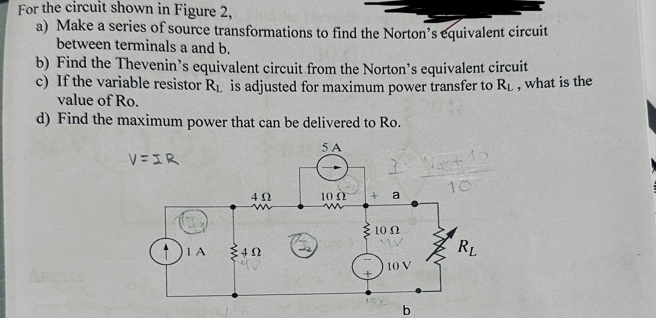
For the circuit shown in Figure
a Make a series of source transformations to find the Norton's equivalent circuit between terminals a and
b Find the Thevenin's equivalent circuit from the Norton's equivalent circuit
c If the variable resistor is adjusted for maximum power transfer to what is the value of Ro
d Find the maximum power that can be delivered to Ro
Please show me the steps in pure detail, the whys and the hows would be amazing to know, thank you so much for your time
Step by Step Solution
There are 3 Steps involved in it
1 Expert Approved Answer
Step: 1 Unlock

Question Has Been Solved by an Expert!
Get step-by-step solutions from verified subject matter experts
Step: 2 Unlock
Step: 3 Unlock