

Question: For the network shown, ( a ) Determine r 0 , in . ( b ) Determine A v m i d . ( c
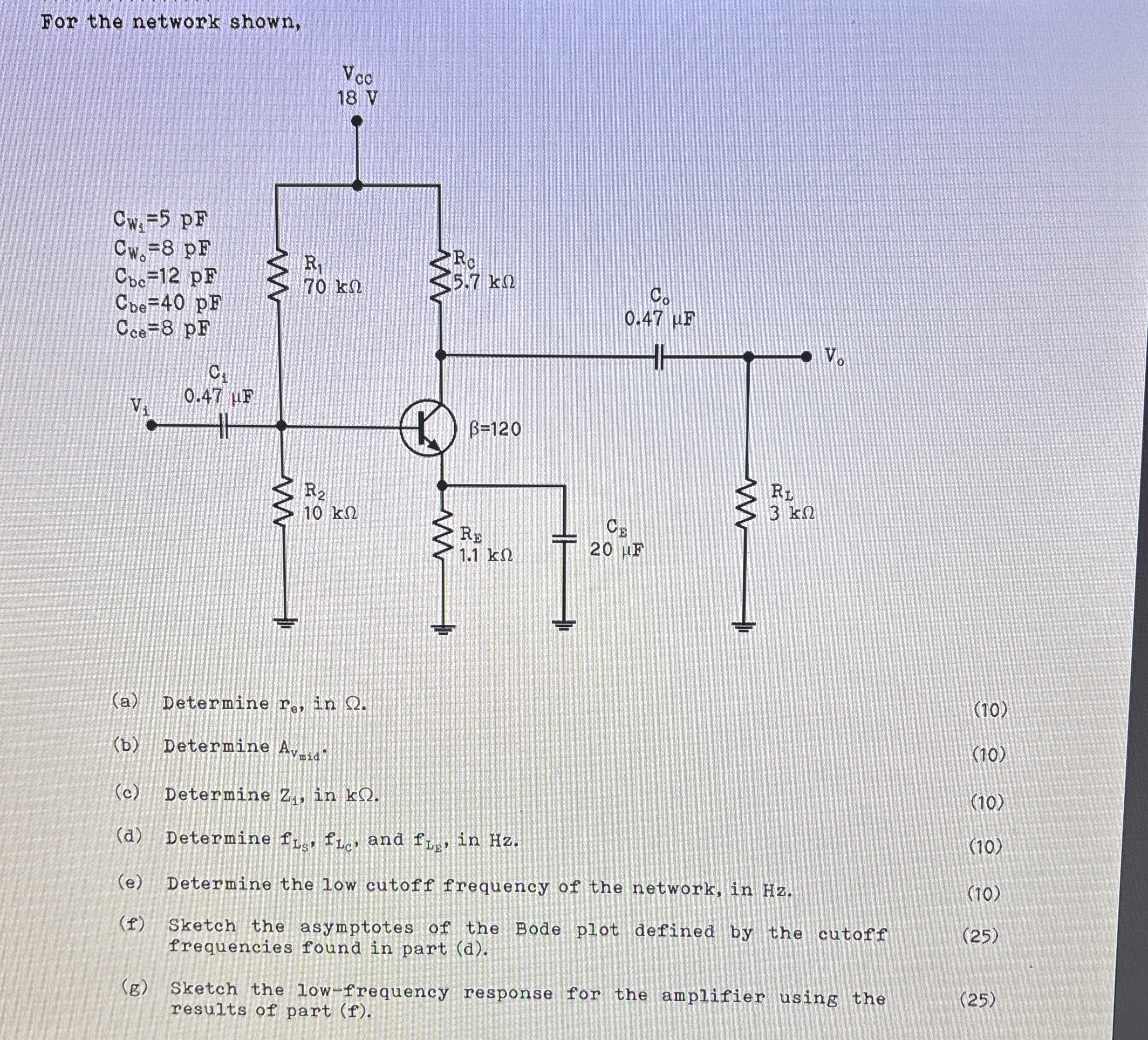
For the network shown,
a Determine in
b Determine
c Determine in
d Determine and in
e Determine the low cutoff frequency of the network, in Hz
f Sketch the asymptotes of the Bode plot defined by the cutoff frequencies found in part d
g Sketch the lowfrequency response for the amplifier using the results of part f
Step by Step Solution
There are 3 Steps involved in it
1 Expert Approved Answer
Step: 1 Unlock

Question Has Been Solved by an Expert!
Get step-by-step solutions from verified subject matter experts
Step: 2 Unlock
Step: 3 Unlock