

Question: For the second half of the lab, create a combinational circuit that carves an instruction into all its possible representations. Since we don't know ahead
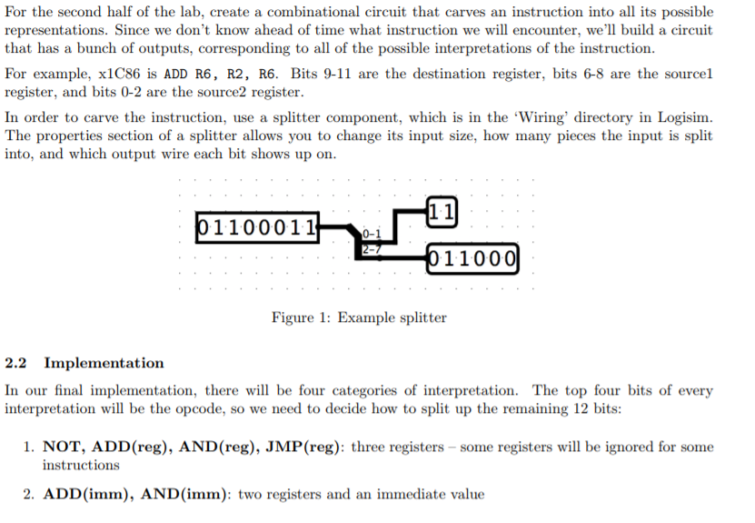
For the second half of the lab, create a combinational circuit that carves an instruction into all its possible representations. Since we don't know ahead of time what instruction we will encounter, we'll build a circuit that has a bunch of outputs, corresponding to all of the possible interpretations of the instruction. For example, x1C86 is ADD R6, R2, R6. Bits 9-11 are the destination register, bits 6-8 are the sourcel register, and bits 0-2 are the source2 register. In order to carve the instruction, use a splitter component, which is in the 'Wiring' directory in Logisim. The properties section of a splitter allows you to change its input size, how many pieces the input is split into, and which output wire each bit shows up on 1.1 1100011 0-1 11000) Figure 1: Example splitter 2.2 Implementation In our final implementation, there w be four categories of interpretation. The top four bits of every interpretation wil be the opcode, so we need to decide how to split up the remaining 12 bits: 1. NOT, ADD(reg), AND(reg), JMP(reg): three registers - some registers will be ignored for some instructions 2. ADD(imm), AND (imm): two registers and an immediate value For the second half of the lab, create a combinational circuit that carves an instruction into all its possible representations. Since we don't know ahead of time what instruction we will encounter, we'll build a circuit that has a bunch of outputs, corresponding to all of the possible interpretations of the instruction. For example, x1C86 is ADD R6, R2, R6. Bits 9-11 are the destination register, bits 6-8 are the sourcel register, and bits 0-2 are the source2 register. In order to carve the instruction, use a splitter component, which is in the 'Wiring' directory in Logisim. The properties section of a splitter allows you to change its input size, how many pieces the input is split into, and which output wire each bit shows up on 1.1 1100011 0-1 11000) Figure 1: Example splitter 2.2 Implementation In our final implementation, there w be four categories of interpretation. The top four bits of every interpretation wil be the opcode, so we need to decide how to split up the remaining 12 bits: 1. NOT, ADD(reg), AND(reg), JMP(reg): three registers - some registers will be ignored for some instructions 2. ADD(imm), AND (imm): two registers and an immediate value
Step by Step Solution
There are 3 Steps involved in it

Get step-by-step solutions from verified subject matter experts