

Question: For the systems shown in Figure (a), design a gain compensator to yield 10-20% overshoot and a state-feedback controller using pole placement topology to produce
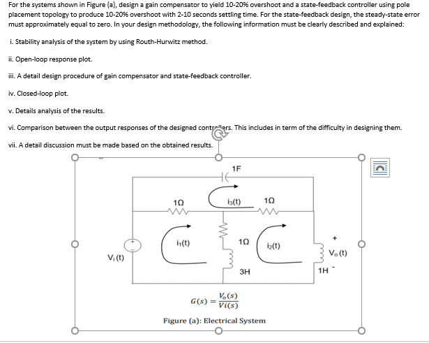
For the systems shown in Figure (a), design a gain compensator to yield 10-20% overshoot and a state-feedback controller using pole placement topology to produce 10-20% overshoot with 2-10 seconds settling time. For the state-feedback design, the steady-state error must approximately equal to zero. In your design methodology, the following information must be clearly described and explained: i. Stability analysis of the system by using Routh-Hurwitz method. ii. Open-loop response plot. iii. A detail design procedure of gain compensator and state-feedback controller. iv. Closed-loop plot. v. Details analysis of the results. vi. Comparison between the output responses of the designed controllers. This includes in term of the difficulty in designing them. vii. A detail discussion must be made based on the obtained results. 1F C 19 13(t) 10 11(t) 10 iz(t) Vi(t) V.(t) 1H G(S) = V.(s) VI(S) Figure (a): Electrical System For the systems shown in Figure (a), design a gain compensator to yield 10-20% overshoot and a state-feedback controller using pole placement topology to produce 10-20% overshoot with 2-10 seconds settling time. For the state-feedback design, the steady-state error must approximately equal to zero. In your design methodology, the following information must be clearly described and explained: i. Stability analysis of the system by using Routh-Hurwitz method. ii. Open-loop response plot. iii. A detail design procedure of gain compensator and state-feedback controller. iv. Closed-loop plot. v. Details analysis of the results. vi. Comparison between the output responses of the designed controllers. This includes in term of the difficulty in designing them. vii. A detail discussion must be made based on the obtained results. 1F C 19 13(t) 10 11(t) 10 iz(t) Vi(t) V.(t) 1H G(S) = V.(s) VI(S) Figure (a): Electrical System
Step by Step Solution
There are 3 Steps involved in it

Get step-by-step solutions from verified subject matter experts