

Question: For the two structures shown below: (a) Draw Free body diagram showing the magnitudes of all applied loads, reaction forces/moments, and parts dimensions. (b)
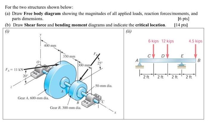
For the two structures shown below: (a) Draw Free body diagram showing the magnitudes of all applied loads, reaction forces/moments, and parts dimensions. (b) Draw Shear force and bending moment diagrams and indicate the critical location. (i) F 11 kN- 20 400 mm Gear A, 600-mm dia. 350 mm 300 mm G Gear B, 300-mm dia. 25 50-mm dia. 6 kips 12 kips 2 ft D [6 pts] [14 pts] 2 ft 2 ft E 4.5 kips 2 ft B
Step by Step Solution
3.52 Rating (166 Votes )
There are 3 Steps involved in it
Solving Question number iFree body diagram Part a Free Body Diagram Identify and label all the applied loads forces and moments on the structure Inclu... View full answer

Get step-by-step solutions from verified subject matter experts