

Question: fully solve this question: Problem 1 System A in Fig. P 1 ( a ) was designed for a mechanical positioning system where x (
fully solve this question:
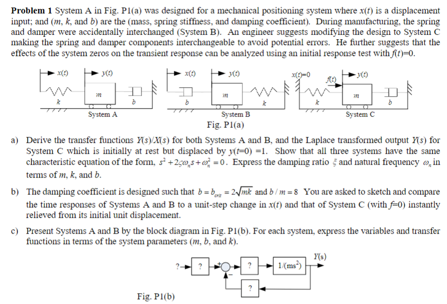
Problem System A in Fig. Pa was designed for a mechanical positioning system where is a displacement
input; and and are the mass spring stiffness, and damping coefficient During manufacturing, the spring
and damper were accidentally interchanged System B An engineer suggests modifying the design to System C
making the spring and damper components interchangeable to avoid potential errors. He further suggests that the
effects of the system zeros on the transient response can be analyzed using an initial response test with
a Derive the transfer functions for both Systems A and B and the Laplace transformed output for
System C which is initially at rest but displaced by Show that all three systems have the same
characteristic equation of the form, Express the damping ratio and natural frequency in
terms of and
b The damping coefficient is designed such that and You are asked to sketch and compare
the time responses of Systems A and B to a unitstep change in and that of System C with instantly
relieved from its initial unit displacement.
c Present Systems A and B by the block diagram in Fig. Pb For each system, express the variables and transfer
functions in terms of the system parameters and
Fig. P
Step by Step Solution
There are 3 Steps involved in it
1 Expert Approved Answer
Step: 1 Unlock

Question Has Been Solved by an Expert!
Get step-by-step solutions from verified subject matter experts
Step: 2 Unlock
Step: 3 Unlock