

Question: (g) Shown below is a two button 'Quiz buzzer circuit. Explain the operation of the We wish to build a 3-bit synchronous counter using edge-triggered
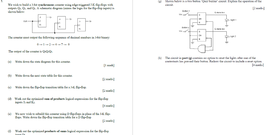
(g) Shown below is a two button 'Quiz buzzer circuit. Explain the operation of the We wish to build a 3-bit synchronous counter using edge-triggered J-K flip-tlops with outputs Q3. Q, and Q1. A schematic diagram (minus the logic for the flip-flop inputs) is shown below: [2 marks] Eutton 1 EN Light 1 Dutton 2 Vos- Q starts low Light 2 The counter must output the following sequencc of decimal numbers in 3-bit binary 012470 The output of the counter is QsQQi h The circuit in part (g) contains no option to reset the lights after one of the contestants has pressed their button. Redraw the circuit to include a reset option. [4 maiks] (a) Write down the state diagram for this counter. 1 mark b Write down the next state table for this counter. [2 marks] (c Write down the flip-flop transition table for a J-K flip-flop [2 marks] (d) Work out the optimized sun of products logical expressions for the flip-flop inputs J and K.. [4 marks] (e We now wish to rebuild this counter using D flip-flops in place of the J-K flip- flops. Write down the flip-flop transition table for a D flip-flop [2 marks] () Work out the optimized products of sums logical expression for the flip-flop
Step by Step Solution
There are 3 Steps involved in it

Get step-by-step solutions from verified subject matter experts