

Question: given instruction step by step on how to build this circuit on breadboard and where to connect the multimeters and the ammeter to test the
given instruction step by step on how to build this circuit on breadboard and where to connect the multimeters and the ammeter to test the voltages and the current, please provide some diagram of the circuit or pictures for better understand of how the circuit should be built on the breadboard.
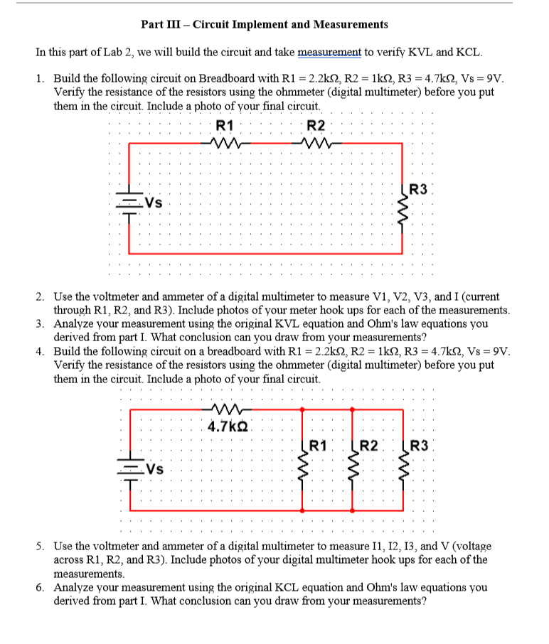
Part III Circuit Implement and Measurements
In this part of Lab we will build the circuit and take measurement to verify KVL and KCL
Build the following circuit on Breadboard with RkOmega,RkOmega,RkOmega,VsV
Verify the resistance of the resistors using the ohmmeter digital multimeter before you put
them in the circuit. Include a photo of vour final circuit.
Use the voltmeter and ammeter of a digital multimeter to measure V V V and I current
through R R and R Include photos of your meter hook ups for each of the measurements.
Analyze your measurement using the original KVL equation and Ohm s law equations you
derived from part I. What conclusion can you draw from your measurements?
Build the following circuit on a breadboard with RkOmega,RkOmega,RkOmega,VsV
Verify the resistance of the resistors using the ohmmeter digital multimeter before you put
them in the circuit. Include a photo of your final circuit.
Use the voltmeter and ammeter of a digital multimeter to measure I I I and V voltage
across R R and R Include photos of your digital multimeter hook ups for each of the
measurements.
Analyze your measurement using the original KCL equation and Ohm's law equations you
derived from part I. What conclusion can you draw from your measurements?
Step by Step Solution
There are 3 Steps involved in it
1 Expert Approved Answer
Step: 1 Unlock

Question Has Been Solved by an Expert!
Get step-by-step solutions from verified subject matter experts
Step: 2 Unlock
Step: 3 Unlock