

Question: Given the problem below, is the attached solution for a ladder logic diagram correct? Consider control of the mixing process of two liquids ( A
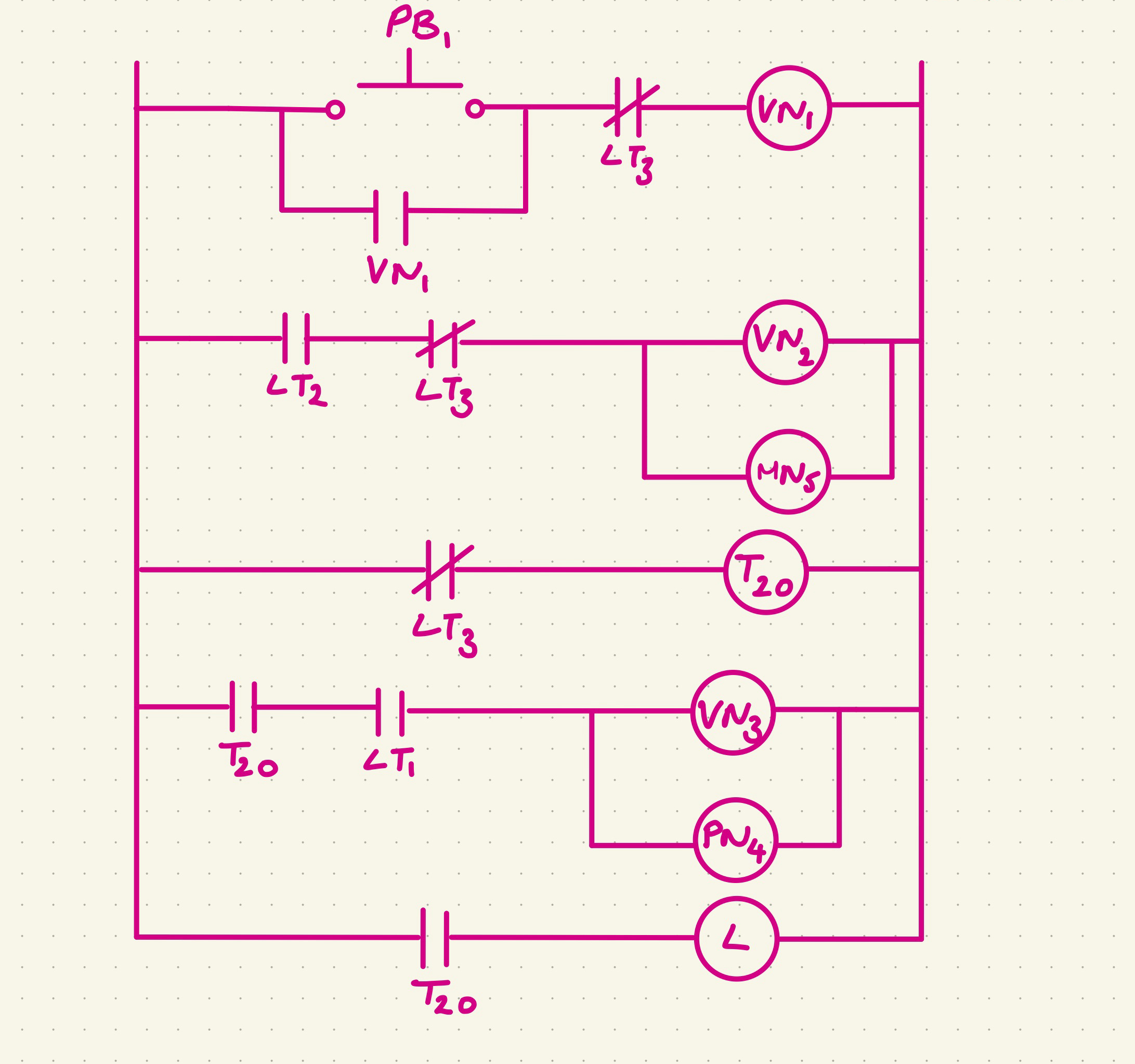
Given the problem below, is the attached solution for a ladder logic diagram correct? Consider control of the mixing process of two liquids A and B shown in the scheme below. At first, on activating a hand switch HS not shown in the diagram liquid A should be introduced VN When the level reaches level LT flow B is started VN At the same time, motor MN is started. When the level reaches LT flow A and flow B are stopped. min after that, the motor is stopped, the discharge valve VN is opened and the pump PN is started. When the level reaches LT the discharge valve VN is closed and the pump PN is stopped. At the same time indicator lamp LAMP not shown in diagram will be on for min indicating that the process is finished.
Step by Step Solution
There are 3 Steps involved in it
1 Expert Approved Answer
Step: 1 Unlock

Question Has Been Solved by an Expert!
Get step-by-step solutions from verified subject matter experts
Step: 2 Unlock
Step: 3 Unlock