

Question: Given the sprinkler system layout in Figure A , calculate the flow and pressure required at point RN# 1 ( point B in Figure B
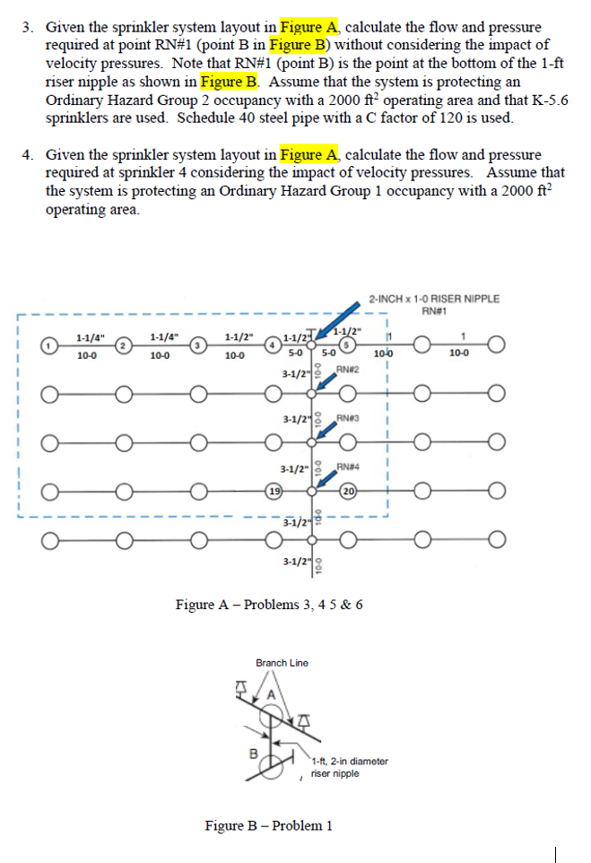
Given the sprinkler system layout in Figure A calculate the flow and pressure required at point RN#point B in Figure B without considering the impact of velocity pressures. Note that RN#point B is the point at the bottom of the ft riser nipple as shown in Figure B Assume that the system is protecting an Ordinary Hazard Group occupancy with a operating area and that K sprinklers are used. Schedule steel pipe with a C factor of is used.
Given the sprinkler system layout in Figure A calculate the flow and pressure required at sprinkler considering the impact of velocity pressures. Assume that the system is protecting an Ordinary Hazard Group occupancy with a operating area.
Figure A Problems &
Figure B Problem
Step by Step Solution
There are 3 Steps involved in it
1 Expert Approved Answer
Step: 1 Unlock

Question Has Been Solved by an Expert!
Get step-by-step solutions from verified subject matter experts
Step: 2 Unlock
Step: 3 Unlock