

Question: Given these data. Please answer the three questions with explanations. Table 1.1 - RUN 1 Increasing Field Current Field Current Output Voltage It (mA) Eg
Given these data. Please answer the three questions with explanations.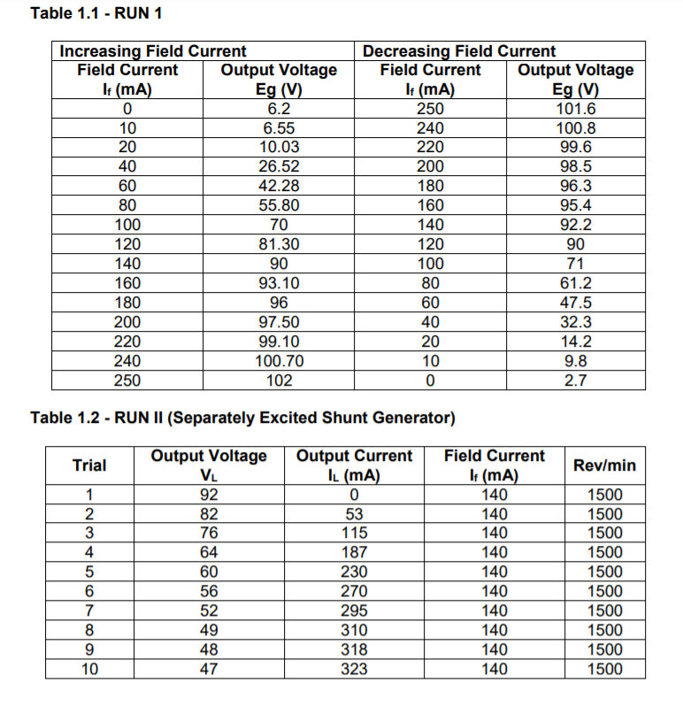
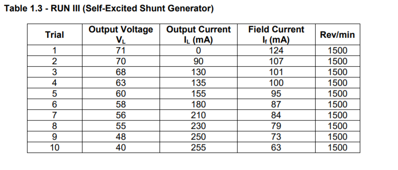
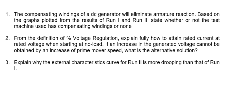
Table 1.1 - RUN 1 Increasing Field Current Field Current Output Voltage It (mA) Eg (V) 0 6.2 10 6.55 20 10.03 40 26.52 60 42.28 80 55.80 100 70 120 81.30 140 90 160 93.10 180 96 200 97.50 220 99.10 240 100.70 250 102 Decreasing Field Current Field Current Output Voltage It (mA) Eg (V) 250 101.6 240 100.8 220 99.6 200 98.5 180 96.3 160 95.4 140 92.2 120 90 100 71 80 61.2 60 47.5 40 32.3 20 14.2 10 9.8 0 2.7 Table 1.2 - RUN II (Separately Excited Shunt Generator) Output Voltage Trial Rev/min VL 1 2 3 4 5 6 7 8 9 10 92 82 76 64 60 56 52 49 48 47 Output Current IL (mA) 0 53 115 187 230 270 295 310 318 323 Field Current It (mA) 140 140 140 140 140 140 140 140 140 140 1500 1500 1500 1500 1500 1500 1500 1500 1500 1500 Table 1.3 -RUN III (Self-Excited Shunt Generator) Trial Rev/min 1 2 3 4 5 6 7 8 9 10 Output Voltage VL 71 70 68 63 60 58 56 55 48 40 Output Current IL (mA) 0 90 130 135 155 180 210 230 250 255 Field Current It (mA) 124 107 101 100 95 87 84 79 73 63 1500 1500 1500 1500 1500 1500 1500 1500 1500 1500 1. The compensating windings of a dc generator will eliminate armature reaction. Based on the graphs plotted from the results of Run I and Run II, state whether or not the test machine used has compensating windings or none 2. From the definition of % Voltage Regulation, explain fully how to attain rated current at rated voltage when starting at no-load. If an increase in the generated voltage cannot be obtained by an increase of prime mover speed, what is the alternative solution? 3. Explain why the external characteristics curve for Run II is more drooping than that of Run 1. Table 1.1 - RUN 1 Increasing Field Current Field Current Output Voltage It (mA) Eg (V) 0 6.2 10 6.55 20 10.03 40 26.52 60 42.28 80 55.80 100 70 120 81.30 140 90 160 93.10 180 96 200 97.50 220 99.10 240 100.70 250 102 Decreasing Field Current Field Current Output Voltage It (mA) Eg (V) 250 101.6 240 100.8 220 99.6 200 98.5 180 96.3 160 95.4 140 92.2 120 90 100 71 80 61.2 60 47.5 40 32.3 20 14.2 10 9.8 0 2.7 Table 1.2 - RUN II (Separately Excited Shunt Generator) Output Voltage Trial Rev/min VL 1 2 3 4 5 6 7 8 9 10 92 82 76 64 60 56 52 49 48 47 Output Current IL (mA) 0 53 115 187 230 270 295 310 318 323 Field Current It (mA) 140 140 140 140 140 140 140 140 140 140 1500 1500 1500 1500 1500 1500 1500 1500 1500 1500 Table 1.3 -RUN III (Self-Excited Shunt Generator) Trial Rev/min 1 2 3 4 5 6 7 8 9 10 Output Voltage VL 71 70 68 63 60 58 56 55 48 40 Output Current IL (mA) 0 90 130 135 155 180 210 230 250 255 Field Current It (mA) 124 107 101 100 95 87 84 79 73 63 1500 1500 1500 1500 1500 1500 1500 1500 1500 1500 1. The compensating windings of a dc generator will eliminate armature reaction. Based on the graphs plotted from the results of Run I and Run II, state whether or not the test machine used has compensating windings or none 2. From the definition of % Voltage Regulation, explain fully how to attain rated current at rated voltage when starting at no-load. If an increase in the generated voltage cannot be obtained by an increase of prime mover speed, what is the alternative solution? 3. Explain why the external characteristics curve for Run II is more drooping than that of Run 1
Step by Step Solution
There are 3 Steps involved in it

Get step-by-step solutions from verified subject matter experts