

Question: Half - Adder: The circuit to be built is called a Half-Adder. This circuit reproduces the operation presented in Table 1, where all the possible
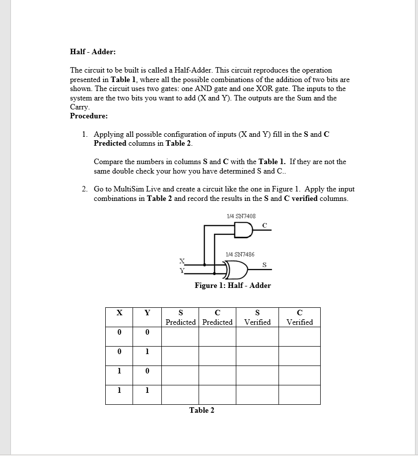

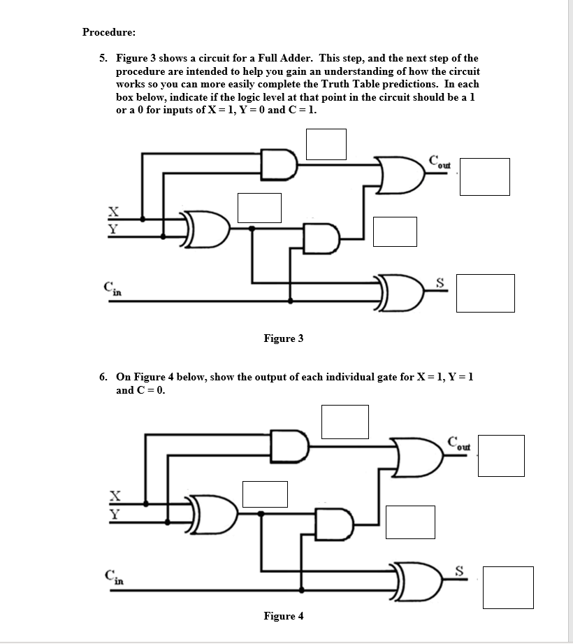
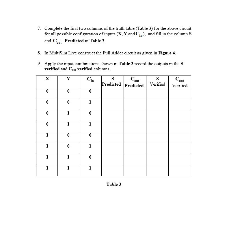
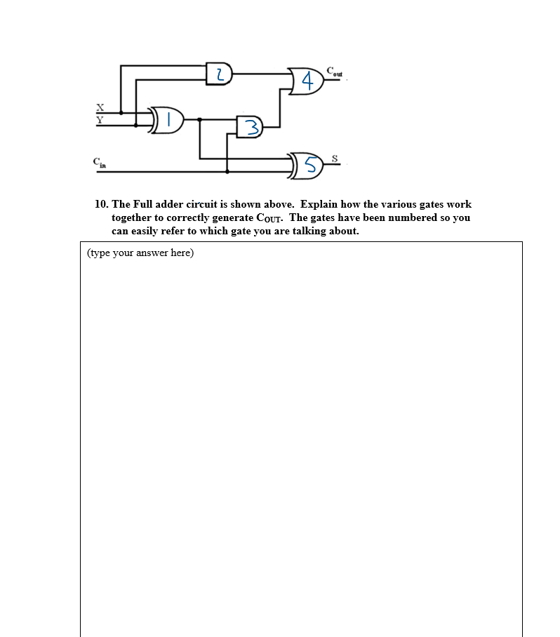
Half - Adder: The circuit to be built is called a Half-Adder. This circuit reproduces the operation presented in Table 1, where all the possible combinations of the addition of two bits are shown. The circuit uses two gates: one AND gate and one XOR gate. The inputs to the system are the two bits you want to add (X and Y). The outputs are the Sum and the Carry. Procedure: 1. Applying all possible configuration of inputs (X and Y) fill in the Sand C Predicted columns in Table 2. Compare the numbers in columns S and C with the Table 1. If they are not the same double check your how you have determined S and C.. 2. Go to MultiSim Live and create a circuit like the one in Figure 1. Apply the input combinations in Table 2 and record the results in the Sand C verified columns. 1/4 SN7408 1/4 SN7486 X Figure 1: Half - Adder X Y s Predicted Predicted s Verified Verified 0 0 0 1 1 0 1 1 Table 2 3. Explain in your own words why the XOR gate output corresponds to the sum bit. (Please explain the concept of what is going on, not simply a reference to the truth table.) (type your answer here) 4. Explain in your own words why the AND gate output corresponds to the carry bit. (Please explain the concept of what is going on, not simply a reference to the truth table.) (type your answer here) Procedure: 5. Figure 3 shows a circuit for a Full Adder. This step, and the next step of the procedure are intended to help you gain an understanding of how the circuit works so you can more easily complete the Truth Table predictions. In each box below, indicate if the logic level at that point in the circuit should be a l or a 0 for inputs of X = 1, Y = 0 and C=1. Cout Y S Figure 3 6. On Figure 4 below, show the output of each individual gate for X = 1, Y = 1 and C=0. Cout tor S Figure 4 7. Complete the first two columns of the truth table (Table 3) for the above circuit for all possible configuration of inputs (X, Y and Cn), and fill in the column S and Cout Predicted in Table 3. 8. In MultiSim Live construct the Full Adder circuit as given in Figure 4. 9. Apply the input combinations shown in Table 3 record the outputs in the S verified and Cout verified columns. X Y S Predicted Cout s Verified Cout Verified Predicted 0 0 0 0 0 1 0 1 0 0 1 1 1 0 0 1 0 1 1 1 0 1 1 1 Table 3 Cout HOTEL Cin 10. The Full adder circuit is shown above. Explain how the various gates work together to correctly generate Cout. The gates have been numbered so you can easily refer to which gate you are talking about. (type your answer here)
Step by Step Solution
There are 3 Steps involved in it

Get step-by-step solutions from verified subject matter experts