

Question: Hand draw the circuit Problem 1 : 5 pts Part 1 : Understanding Logisim Logisim ( logic simulator ) is a software program for
Hand draw the circuit
Problem : pts
Part : Understanding Logisim Logisim logic simulator" is a software program for designing
combinational circuits. We will use Logism in this lab and the next lab to help us design complex
circuits. The purpose of this section is to help you become comfortable with Logisim.
Part : Boolean Formulas and Truth Tables do it by hand
As you saw in the lecture, every Boolean function has three equivalent representations: a
Boolean formula, a Boolean circuit, and a truth table. One simple example of a Boolean function
is the majority function. Given n inputs, the majority function is true if more than half the
inputs are true; otherwise it is false.
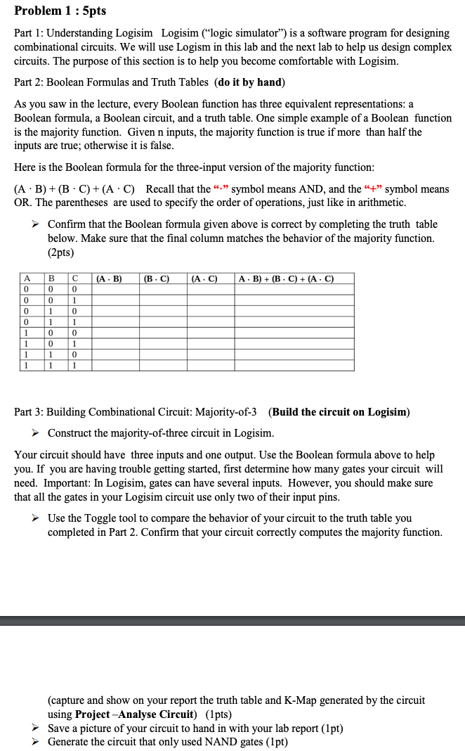
Here is the Boolean formula for the threeinput version of the majority function:
ABBCACquad Recall that the symbol means AND, and the symbol means
OR The parentheses are used to specify the order of operations, just like in arithmetic.
Confirm that the Boolean formula given above is correct by completing the truth table
below. Make sure that the final column matches the behavior of the majority function.
pts
Part : Building Combinational Circuit: MajorityofBuild the circuit on Logisim
Construct the majorityofthree circuit in Logisim.
Your circuit should have three inputs and one output. Use the Boolean formula above to help
you. If you are having trouble getting started, first determine how many gates your circuit will
need. Important: In Logisim, gates can have several inputs. However, you should make sure
that all the gates in your Logisim circuit use only two of their input pins.
Use the Toggle tool to compare the behavior of your circuit to the truth table you
completed in Part Confirm that your circuit correctly computes the majority function.
capture and show on your report the truth table and KMap generated by the circuit
using ProjectAnalyse Circuitpts
Save a picture of your circuit to hand in with your lab report pt
Generate the circuit that only used NAND gates pt
Step by Step Solution
There are 3 Steps involved in it
1 Expert Approved Answer
Step: 1 Unlock

Question Has Been Solved by an Expert!
Get step-by-step solutions from verified subject matter experts
Step: 2 Unlock
Step: 3 Unlock