

Question: Hardware Setup and I/O-Use three momentary switches (or one multi-way switch) to drive speaker SP1 from a GPIO output (labeled Audio below). Capacitor C1 should
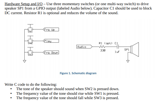
Hardware Setup and I/O-Use three momentary switches (or one multi-way switch) to drive speaker SP1 from a GPIO output (labeled Audio below). Capacitor C1 should be used to block DC current. Resistor R1 is optional and reduces the volume of the sound. Frg Up Oo Play Ri (opt) C1 SW2 I o o SW3 Audio Audio master y sent 338 SPI Frg Down lt Figure 1. Schematic diagram Write C code to do the following: The tone of the speaker should sound when SW2 is pressed down. . The frequency value of the tone should rise while SW1 is pressed. The frequency value of the tone should fall while SW3 is pressed. Hardware Setup and I/O-Use three momentary switches (or one multi-way switch) to drive speaker SP1 from a GPIO output (labeled Audio below). Capacitor C1 should be used to block DC current. Resistor R1 is optional and reduces the volume of the sound. Frg Up Oo Play Ri (opt) C1 SW2 I o o SW3 Audio Audio master y sent 338 SPI Frg Down lt Figure 1. Schematic diagram Write C code to do the following: The tone of the speaker should sound when SW2 is pressed down. . The frequency value of the tone should rise while SW1 is pressed. The frequency value of the tone should fall while SW3 is pressed
Step by Step Solution
There are 3 Steps involved in it

Get step-by-step solutions from verified subject matter experts