

Question: Hello I'm using HCS12 Dragon light board and I'm using AsmIDE assembly to code for it. I need help with this problem, the code isn't
Hello I'm using HCS12 Dragon light board and I'm using AsmIDE assembly to code for it. I need help with this problem,
the code isn't working as how the prompt is. I included the question and the code that i have. I need an interrupt code in assembly, but im not sure what I'm doing is correct
Here is the code that i have
#include Reg9s12.H
;----------------------USE $1000-$2FFF for Scratch Pad and Stack BLANK EQU $1000 LED0 EQU $1008 LED1 EQU $1007 LED2 EQU $1006 LED3 EQU $1005 LED4 EQU $1004 LED5 EQU $1003 LED6 EQU $1002 LED7 EQU $1001
TEMP EQU $1010
ORG #$2000 LDS #$2000 ;Stack
MOVB #$00, BLANK MOVB #$3F, LED0 MOVB #$06, LED1 MOVB #$5B, LED2 MOVB #$4F, LED3 MOVB #$66, LED4 MOVB #$6D, LED5 MOVB #$7D, LED6 MOVB #$07, LED7
LDAA #$00 STAA DDRE LDAA #$FF STAA DDRB ;MAKE PORTB AN OUTPUT PORT STAA DDRP ;PTP as Output LDX #$1000 ;INTERRUPT SET-UP FOR RTI ANDCC #%10111111
BACK LDAA #$00 STAA PORTB LDAA #$5F STAA PTP BRA BACK
XIRQ LDAA #$5F SUBA PTP BNE EXIT
LDAB PORTE ANDB #%01110000 LSRB LSRB LSRB LSRB
LDAA #$10 INCB STD TEMP LDX TEMP
LDAA 0,X STAA PORTB LDAA #%00010111 STAA PTP ;PTP as Output
EXIT RTI
;************************************************************** ;************************************************************** ;************************************************************** ;************************************************************** ;************************************************************** ;************************************************************** ;************************************************************** ;**************************************************************
; START:
R1 EQU $1001 R2 EQU $1002 R3 EQU $1003
Org $2000
DispTab dc.b $3F,$06,$5B,$4F,$66,$6D,$7D,$07,$7F,$6F ;$6F,$7F,$07,$7D,$6D,$66,$4F,$5B,$06,$3F ; counting down ;$3F,$06,$5B,$4F,$66,$6D,$7D,$07,$7F,$6F ; counting up
org $2500 lds #$2000 movb #$FF,DDRB ; Configure port B as output port movb #$00,DDRP ; configure PP0 to PP3 as output pins movb #$FE,PTP ; enable the display #0 bset DDRJ,$02 ; configure PJ1 pin for output bset PTJ,$02 ; disable the LEDs
forever ldx #DispTab ; set X to point to the display table
loopi movb 0,x,PORTB ; output segment pattern inx ldy #1000 jsr Delay ; wait for 1 second jsr Delay jsr Delay jsr Delay jsr Delay jsr Delay jsr Delay jsr Delay cpx #DispTab+10 ; reach the end of the table? bne loopi bra forever
Delay PSHA ; Save Reg A on Stack LDAA #1 STAA R3
;--10 msec delay. The D-Bug12 works at speed of 48MHz ; with XTAL=8MHz on Dragon12+ board
;Freq. for Instruction Clock Cycle (and Bus Cycle) ;is 24MHz (1/2 of 48Mhz).
;(1/24MHz) x 250 Clk x240x100= 125 msec. ; Overheads are excluded in this calculation.
L3 LDAA #250 STAA R2
L2 LDAA #240 STAA R1
L1 NOP ; 1 Intruction Clk Cycle Cycl NOP ; 1 NOP ; 1 DEC R1 ; 4 BNE L1 ; 3 DEC R2 ; Total Instr.Clk=10 BNE L2 DEC R3 BNE L3 ;------------------------------------------------------------ PULA ; Restore Reg A RTS ;------------------------------------------------------------
;********************************;****************************** ;In HCS12, the Interrupts go to the Interrupt vector table in $FFFF-FFxx ROM addres area. ;However,the D-Bug12 redirects them to RAM space area of $3Exx-3Exx ;We must redirect them from these areas to our ISR. ; ;* Interrupt Vector Table Addresses for D-Bug12 are on page 365 of Mazidi & Causey HCS12 textbook ;************************************************************** ORG $3E74 ;3E72 FOR IRQ DC.W XIRQ ; DC.W IRQ_EDGE ; ORG ;Vector table location for RTI interupt is 3E4C (See page 365 of Mazidi & Causey HCS12 textbook)
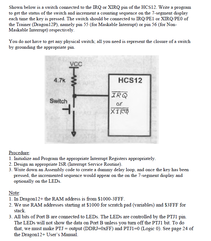
Shown below is a switch connected to the IRQ or XIRQ pin of the HCS12. Write a program to get the status of the switch and increment a counting sequence on the 7-segment display each time the key is pressed. The switch should be connected to IRQ/PE1 or IRQ/PEO of the Trainer (Dragon12P), namely pin 55 (for Maskable Interrupt) or pin 56 (for Non Maskable Interrupt) respectively You do not have to get any physical switch; all you need is represent the closure of a switch by grounding the appropriate pin. 4.7k HCS12 IRO ar XTRG Switch -l Procedure 1. Initialize and Program the appropriate Interrupt Registers appropriately 2. Design an appropriate ISR (Interrupt Service Routine) 3. Write down an Assembly code to create a dummy delay loop, and once the key has been essed, the incremented sequence would appear on the on the 7-segment display and optionally on the LEDs. Note 1. In Dragon12+ the RAM address is from $1000-3FFF 2. We use RAM addresses starting at $1000 for scratch pad (variables) and $3FFF for stack 3. All bits of Port B are connected to LEDs. The LEDs are controlled by the PTJ1 pin. The LEDs wll not show the data on Port B unless you turn off the PTJ1 bit. To do that, we must make PTI = output (DDRJ=0xFF) and PTJ 1-0 (Logic 0). See page 24 of the Dragon12+ User's Manual. Shown below is a switch connected to the IRQ or XIRQ pin of the HCS12. Write a program to get the status of the switch and increment a counting sequence on the 7-segment display each time the key is pressed. The switch should be connected to IRQ/PE1 or IRQ/PEO of the Trainer (Dragon12P), namely pin 55 (for Maskable Interrupt) or pin 56 (for Non Maskable Interrupt) respectively You do not have to get any physical switch; all you need is represent the closure of a switch by grounding the appropriate pin. 4.7k HCS12 IRO ar XTRG Switch -l Procedure 1. Initialize and Program the appropriate Interrupt Registers appropriately 2. Design an appropriate ISR (Interrupt Service Routine) 3. Write down an Assembly code to create a dummy delay loop, and once the key has been essed, the incremented sequence would appear on the on the 7-segment display and optionally on the LEDs. Note 1. In Dragon12+ the RAM address is from $1000-3FFF 2. We use RAM addresses starting at $1000 for scratch pad (variables) and $3FFF for stack 3. All bits of Port B are connected to LEDs. The LEDs are controlled by the PTJ1 pin. The LEDs wll not show the data on Port B unless you turn off the PTJ1 bit. To do that, we must make PTI = output (DDRJ=0xFF) and PTJ 1-0 (Logic 0). See page 24 of the Dragon12+ User's Manual
Step by Step Solution
There are 3 Steps involved in it

Get step-by-step solutions from verified subject matter experts