

Question: Help!!!!!! please answer this all question, ref directions are given read carefully OEMP Part 2 Individual Written Responses (10 points) . Discuss whether any members
Help!!!!!! please answer this all question, ref directions are given read carefully
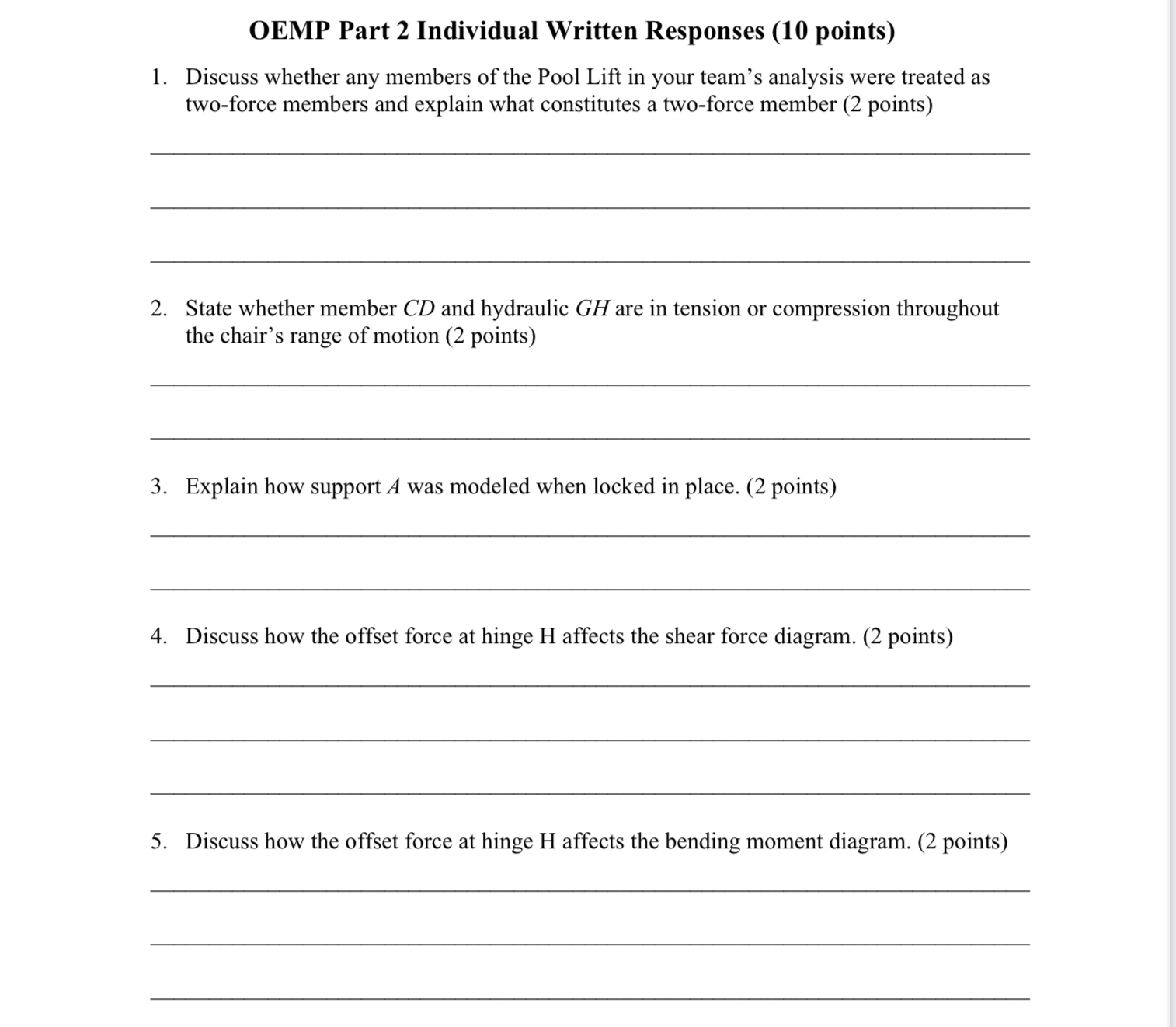


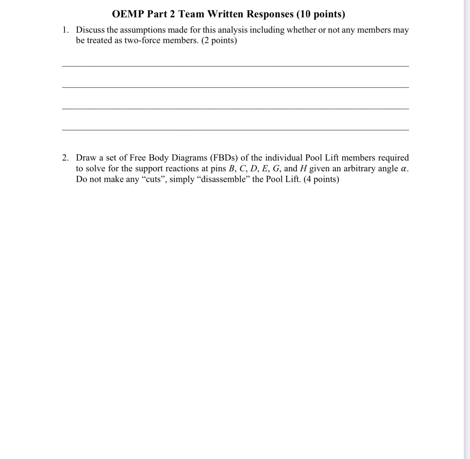
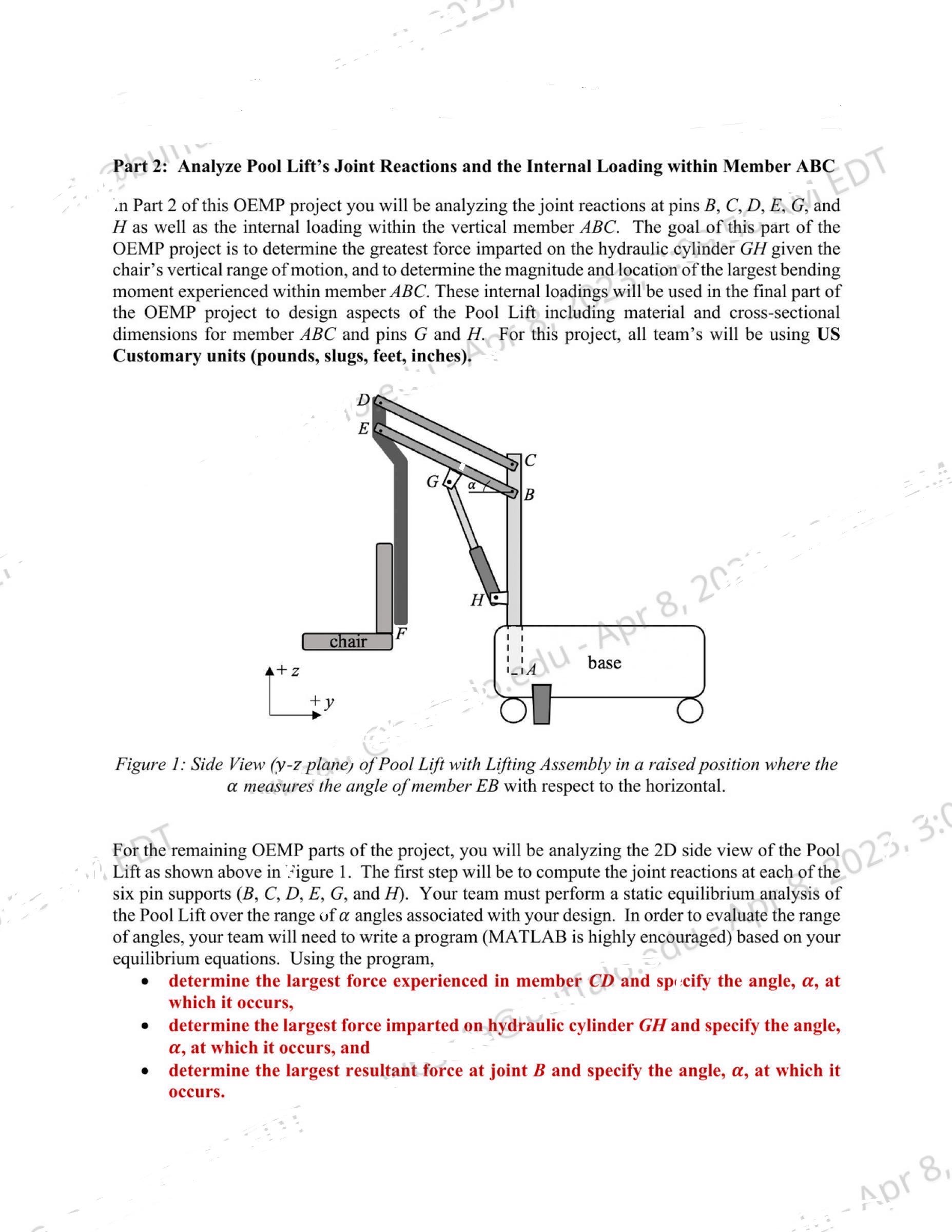
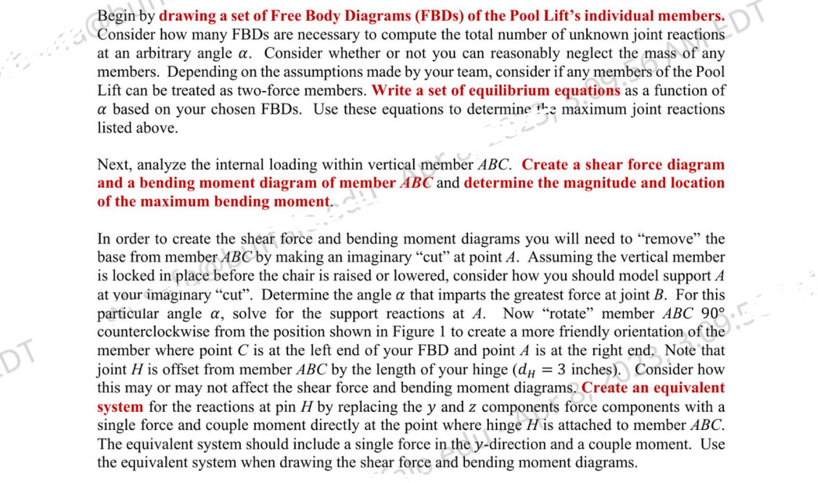
OEMP Part 2 Individual Written Responses (10 points) . Discuss whether any members of the Pool Lift in your team's analysis were treated as twoforce members and explain what constitutes a two-force member (2 points) . State whether member CD and hydraulic GH are in tension or compression throughout the chair's range of motion (2 points) . Explain how support A was modeled when locked in place. (2 points) . Discuss how the offset force at hinge H affects the shear force diagram. (2 points) . Discuss how the offset force at hinge H affects the bending moment diagram. (2 points) OEMP Part 2 Team Written Responses (10 points) 1. Discuss the assumptions made for this analysis including whether or not any members may be treated as two-force members. (2 points) 2. Draw a set of Free Body Diagrams (FBDs) of the individual Pool Lift members required to solve for the support reactions at pins 3, C, D, E, G, and H given an arbitrary angle a. Do not make any \"cuts\Part 2: Analyze Pool Lift's Joint Reactions and the Internal Loading within Member ABC in Part 2 of this OEMIJ project you will be analyzing the joint reactions at pins B, C, D, E, G, and H as well as the internal loading within the vertical member ABC. The goal of this part of the OEMP project is to determine the greatest force imparted on the hydraulic cylinder GH given the Chair's vertical range of motion, and to determine the magnitude and location of the largest bending moment experienced within member ABC. These internal loadings will be used in the nal part of the OEMP project to design aspects of the Pool Li including material and cross-sectional dimensions for member ABC and pins G and H. For this project, all team's will be using US Customary units (pounds, slugs, feet, inches). Figure 1: Side View (yz plane; ofPool Li' with Lifting Assembly in a raised position where the as measures the angle quember EB with respect to the horizontal. For the remaining OEMP parts of the project, you will be analyzing the 2D side view of the Pool Lift as shown above in Figure l. The rst step will be to compute the joint reactions at each of the six pin supports (B, C, D, E, G, and H). Your team must perform a static equilibrium analysis of the Pool Lift over the range of at angles associated with your design. In order to evaluate the range of angles, your team will need to write a program (MATLAB is highly encouraged) based on your equilibrium equations. Using the program, 0 determine the largest force experienced in member CD and spiccify the angle, a, at which it occurs, 0 determine the largest force imparted on hydraulic cylinder GH and specify the angle, a, at which it occurs, and 0 determine the largest resultant force at joint B and specify the angle, a, at which it occurs. Begin by drawing a set of Free Body Diagrams (FBDs) of the Pool Lift's individual members. Consider how many F BDs are necessary to compute the total number of unknown joint reactions at an arbitrary angle (I. Consider whether or not you can reasonably neglect the mass of any members. Depending on the assumptions made by your team, consider if any members of the Pool Lift can be treated as two-force members. Write a set of equilibrium equations as a function of at based on your chosen FBDs. Use these equations to determine the maximum joint reactions listed above. Next, analyze the internal loading within vertical member ABC. Create a shear force diagram and a bending moment diagram of member ABC and determine the magnitude and location of the maximum bending moment. In order to create the shear force and bending moment diagrams you will need to \"remove\" the base from member ABC by making an imaginary \"cut\" at point A. Assuming the vertical member is locked in place before the chair is raised or lowered, consider how you should model support A at your imaginary \"out". Determine the angle a that imparts the greatest force at joint B. For this particular angle at, solve for the support reactions at A. Now \"rotate\" member ABC 90 counterclockwise from the position shown in Figure 1 to create a more friendly orientation of the member where point C is at the left end of your FBD and point A is at the right end. Note that joint H is offset from member ABC by the length of your hinge (dH = 3 inches). Consider how this may or may not affect the shear force and bending moment diagrams. Create an equivalent system for the reactions at pin H by replacing the y and 2 components force components with a single force and couple moment directly at the point where hinge H is attached to member ABC. The equivalent system should include a single force in the y-direction and a couple moment. Use the equivalent system when drawing the shear force and bending moment diagrams
Step by Step Solution
There are 3 Steps involved in it

Get step-by-step solutions from verified subject matter experts