

Question: here is 1d below answer the a in the first picture not. not 1a a. This MSP430F5529 has been configured to use an 8MHz crystal

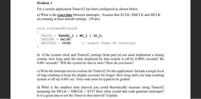
a. This MSP430F5529 has been configured to use an 8MHz crystal for XT2 (instead of 4 MHZ like the Launchpad). Write a function to configure the UCS registers to turn on XT2 and set SMCLK to use XT2 as it's clock source (i.e. set SMCLK = 8 MHz). Don't forget to set P5.5-2 as shown in Id. Problem 1 For a certain application TimerA2 has been configured as shown below. a) What is the exact time between interrupts. Assume that ACLK, SMCLK and MCLK are running at their default settings. (30 pts) void runtimerA2 (void) TAZCTL - TASSEL_1 | MC_1 | ID_0; TA2CCRO - 0x13F; TA2CCTLO - CCIE V/ enable Timer A2 interrupt 1 b) If the system clock and TimerA2 settings from part (a) are used implement a timing system, how long until the time displayed by that system is off by 0.0005 seconds? By 0.001 seconds? Will the system be fast or slow? How do you know? e) Write the interrupt service routine for TimerA2 for this application, Include a single level of leap counting to keep the display accurate for longer. How long until you leap counting system is off my 0.001 sec. Your code must be typed to be graded. d) What is the smallest time interval you could theoretically measure using TimerA2 assuming the MCLK - SMCLK = XT2? How often would that code generate interrupts? Is it a good idea to set the Timer to that interval? Explain
Step by Step Solution
There are 3 Steps involved in it

Get step-by-step solutions from verified subject matter experts