

Question: C. FIGURE Q1 shows a half-wave controlled rectifier circuit using 2 SCRs, one is used for rectification and other is as free-wheeling device. ti
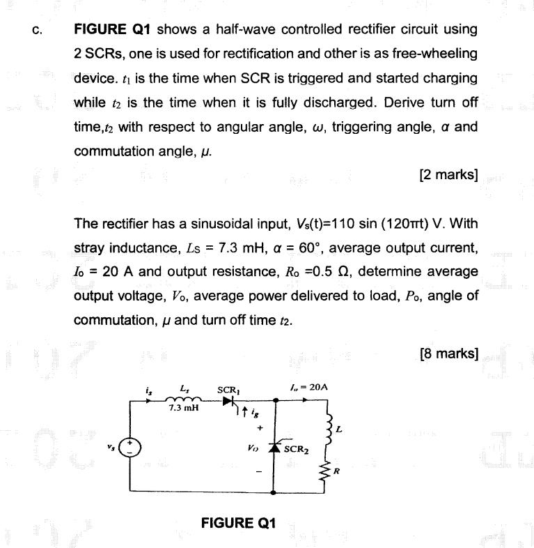
C. FIGURE Q1 shows a half-wave controlled rectifier circuit using 2 SCRs, one is used for rectification and other is as free-wheeling device. ti is the time when SCR is triggered and started charging while t2 is the time when it is fully discharged. Derive turn off time,t2 with respect to angular angle, w, triggering angle, a and commutation angle, u. The rectifier has a sinusoidal input, Vs(t)=110 sin (120t) V. With stray inductance, Ls = 7.3 mH, a = 60, average output current, Io = 20 A and output resistance, Ro =0.5 , determine average output voltage, Vo, average power delivered to load, Po, angle of commutation, and turn off time t2. H i, L 7.3 mH SCRI + Vo FIGURE Q1 /,= 20A [2 marks] SCR [8 marks]
Step by Step Solution
3.42 Rating (152 Votes )
There are 3 Steps involved in it
SOLUTION c Given Vs 12 Solution when is Ls mm 73 MH ... View full answer

Get step-by-step solutions from verified subject matter experts