

Question: Hi could someone offer a step by step solution for this Question? Thanks! ITOTAL MARKS: 25] 15 Marks] QUESTION 2 Q2(a) BCD b BCD C
Hi could someone offer a step by step solution for this Question? Thanks!
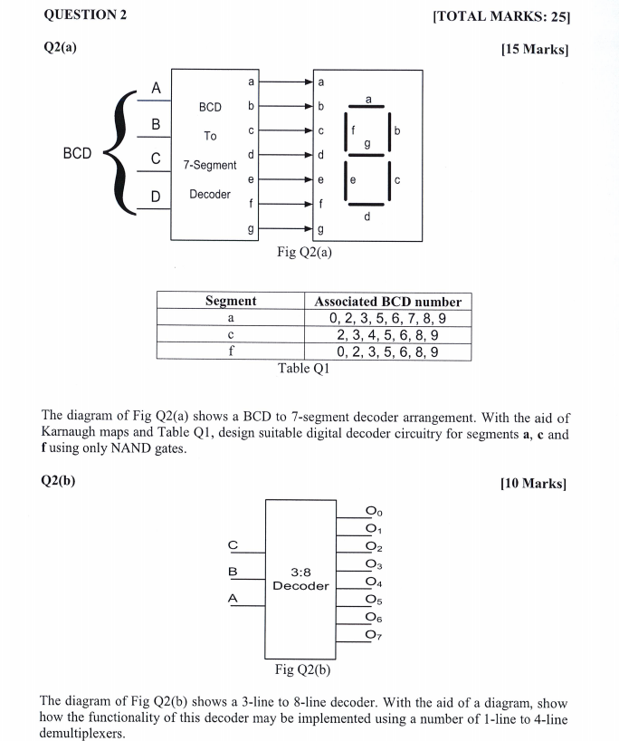
ITOTAL MARKS: 25] 15 Marks] QUESTION 2 Q2(a) BCD b BCD C 7-Segment DI Decoder Fig Q2(a) Segment Associated BCD number 0, 2, 3, 5, 6, 7, 8,59 2, 3, 4, 5, 6, 8,9 0, 2, 3, 5, 6, 8,9 Table Q1 The diagram of Fig Q2(a) shows a BCD to 7-segment decoder arrangement. With the aid of Karnaugh maps and Table Q1, design suitable digital decoder circuitry for segments a, c and fusing only NAND gates Q2(b) 10 Marks] 3:8 Decoder Fig Q2(b) The diagram of Fig Q2(b) shows a 3-line to 8-line decoder. With the aid of a diagram, show how the functionality of this decoder may be implemented using a number of 1-line to 4-line demultiplexers ITOTAL MARKS: 25] 15 Marks] QUESTION 2 Q2(a) BCD b BCD C 7-Segment DI Decoder Fig Q2(a) Segment Associated BCD number 0, 2, 3, 5, 6, 7, 8,59 2, 3, 4, 5, 6, 8,9 0, 2, 3, 5, 6, 8,9 Table Q1 The diagram of Fig Q2(a) shows a BCD to 7-segment decoder arrangement. With the aid of Karnaugh maps and Table Q1, design suitable digital decoder circuitry for segments a, c and fusing only NAND gates Q2(b) 10 Marks] 3:8 Decoder Fig Q2(b) The diagram of Fig Q2(b) shows a 3-line to 8-line decoder. With the aid of a diagram, show how the functionality of this decoder may be implemented using a number of 1-line to 4-line demultiplexers
Step by Step Solution
There are 3 Steps involved in it

Get step-by-step solutions from verified subject matter experts