

Question: Homework 1: Write out the code to set these pins to digital outputs (assume segments are connected in order)-Zn C R. 2: Assuming the LED
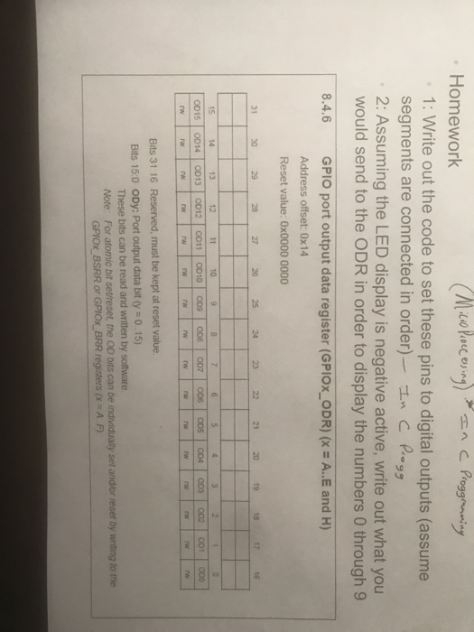
Homework 1: Write out the code to set these pins to digital outputs (assume segments are connected in order)-Zn C R. 2: Assuming the LED display is negative active, write out what you would send to the ODR in order to display the numbers 0 through 9 8.4.6 GPIO port output data register (GPIOxODR) (x = A..E and H) Address offset: 0x14 Reset value: 0x0000 0000 31 30 29 28 27 26 25 24 23 22 21 20 19 1817 16 14 13 12 10 0015 | 0014 | 0013 | 0012 | 0011 | 0010 | 009 'es | 7 | OD6 | 005 | oos | 002 | 001 | 000 rw rw Bits 31:16 Reserved, must be kept at reset value Bits 15:0 ODy: Port output data bit ty 015) These bits can be read and written by software Note: For atomic bit setreset, the OD bits can be individualy set and/or reset by wnting to the GPIOX BSRR or GPIOX BRR registers (x-A.F) Homework 1: Write out the code to set these pins to digital outputs (assume segments are connected in order)-Zn C R. 2: Assuming the LED display is negative active, write out what you would send to the ODR in order to display the numbers 0 through 9 8.4.6 GPIO port output data register (GPIOxODR) (x = A..E and H) Address offset: 0x14 Reset value: 0x0000 0000 31 30 29 28 27 26 25 24 23 22 21 20 19 1817 16 14 13 12 10 0015 | 0014 | 0013 | 0012 | 0011 | 0010 | 009 'es | 7 | OD6 | 005 | oos | 002 | 001 | 000 rw rw Bits 31:16 Reserved, must be kept at reset value Bits 15:0 ODy: Port output data bit ty 015) These bits can be read and written by software Note: For atomic bit setreset, the OD bits can be individualy set and/or reset by wnting to the GPIOX BSRR or GPIOX BRR registers (x-A.F)
Step by Step Solution
There are 3 Steps involved in it

Get step-by-step solutions from verified subject matter experts