

Question: How to simulate the below process in Aspen Plus? Any assumptions possible. The project A plant is to be designed to produce 20 million standard
How to simulate the below process in Aspen Plus?
Any assumptions possible.
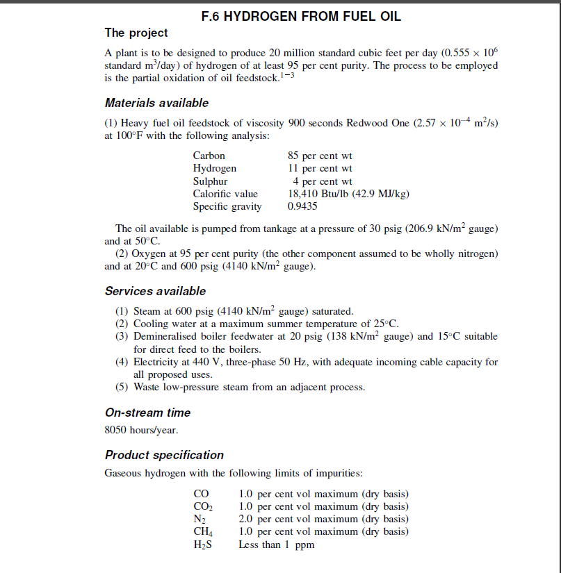
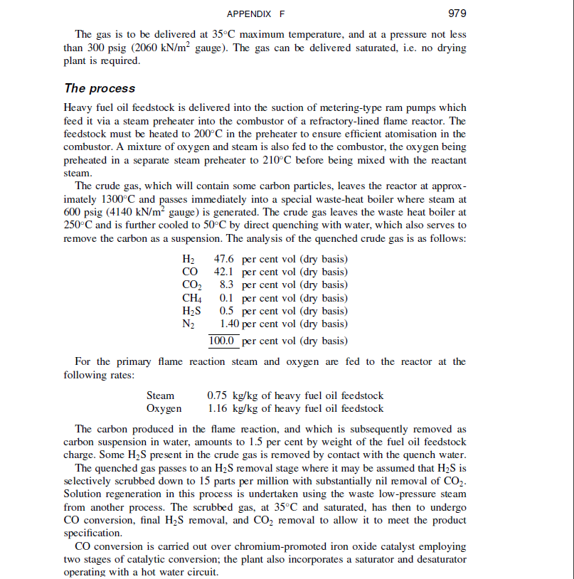
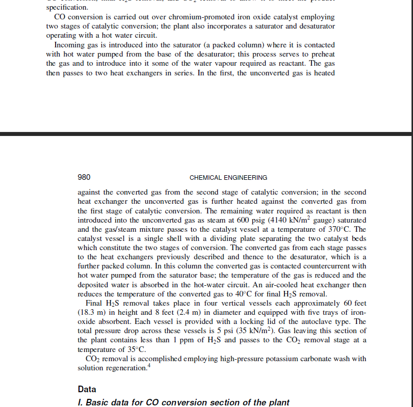
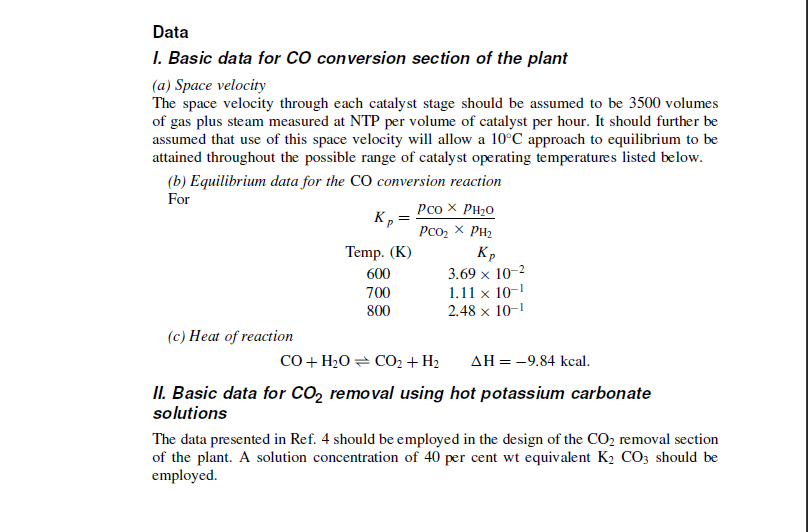
The project A plant is to be designed to produce 20 million standard cubic feet per day (0.555106 standard m3/ day) of hydrogen of at least 95 per cent purity. The process to be employed is the partial oxidation of oil feedstock. 13 Materials available (1) Heavy fuel oil feedstock of viscosity 900 seconds Redwood One (2.57104m2/s) at 100F with the following analysis: The oil available is pumped from tankage at a pressure of 30psig(206.9kN/m2 gauge) and at 50C. (2) Oxygen at 95 per cent purity (the other component assumed to be wholly nitrogen) and at 20C and 600psig(4140kN/m2 gauge). Services available (1) Steam at 600psig(4140kN/m2 gauge) saturated. (2) Cooling water at a maximum summer temperature of 25C. (3) Demineralised boiler feedwater at 20psig(138kN/m2 gauge) and 15C suitable for direct feed to the boilers. (4) Electricity at 440V, three-phase 50Hz, with adequate incoming cable capacity for all proposed uses. (5) Waste low-pressure steam from an adjacent process. On-stream time 8050 hours/year. Product specification Gaseous hydrogen with the following limits of impurities: The gas is to be delivered at 35C maximum temperature, and at a pressure not less than 300psig(2060kN/m2 gauge). The gas can be delivered saturated, i.e. no drying plant is required. The process Heavy fuel oil feedstock is delivered into the suction of metering-type ram pumps which feed it via a steam preheater into the combustor of a refractory-lined flame reactor. The feedstock must be heated to 200C in the preheater to ensure efficient atomisation in the combustor. A mixture of oxygen and steam is also fed to the combustor, the oxygen being preheated in a separate steam preheater to 210C before being mixed with the reactant steam. The crude gas, which will contain some carbon particles, leaves the reactor at approximately 1300C and passes immediately into a special waste-heat boiler where steam at 600psig(4140kN/m2 gauge) is generated. The crude gas leaves the waste heat boiler at 250C and is further cooled to 50C by direct quenching with water, which also serves to remove the carbon as a suspension. The analysis of the quenched crude gas is as follows: For the primary flame reaction steam and oxygen are fed to the reactor at the following rates: Steam 0.75kg/kg of heavy fuel oil feedstock Oxygen 1.16kg/kg of heavy fuel oil feedstock The carbon produced in the flame reaction, and which is subsequently removed as carbon suspension in water, amounts to 1.5 per cent by weight of the fuel oil feedstock charge. Some H2S present in the crude gas is removed by contact with the quench water. The quenched gas passes to an H2S removal stage where it may be assumed that H2S is selectively scrubbed down to 15 parts per million with substantially nil removal of CO2. Solution regeneration in this process is undertaken using the waste low-pressure steam from another process. The scrubbed gas, at 35C and saturated, has then to undergo CO conversion, final H2S removal, and CO2 removal to allow it to meet the product specification. CO conversion is carried out over chromium-promoted iron oxide catalyst employing two stages of catalytic conversion; the plant also incorporates a saturator and desaturator operating with a hot water circuit. specification. CO conversion is carried out over chromium-promoted iron oxide catalyst employing two stages of catalytic conversion; the plant also incorporates a saturator and desaturator operating with a hot water circuit. Incoming gas is introduced into the saturator (a packed column) where it is contacted with hot water pumped from the base of the desaturator; this process serves to preheat the gas and to introduce into it some of the water vapour required as reactant. The gas then passes to two heat exchangers in series. In the first, the unconverted gas is heated 980 CHEMICAL ENGINEERING against the converted gas from the second stage of catalytic conversion; in the second heat exchanger the unconverted gas is further heated against the converted gas from the first stage of catalytic conversion. The remaining water required as reactant is then introduced into the unconverted gas as steam at 600psig(4140kN/m2 gauge ) saturated and the gas/steam mixture passes to the catalyst vessel at a temperature of 370C. The catalyst vessel is a single shell with a dividing plate separating the two catalyst beds which constitute the two stages of conversion. The converted gas from each stage passes to the heat exchangers previously described and thence to the desaturator, which is a further packed column. In this column the converted gas is contacted countercurrent with hot water pumped from the saturator base; the temperature of the gas is reduced and the deposited water is absorbed in the hot-water circuit. An air-cooled heat exchanger then reduces the temperature of the converted gas to 40C for final H2S removal. Final H2S removal takes place in four vertical vessels each approximately 60 feet (18.3m) in height and 8 feet (2.4m) in diameter and equipped with five trays of ironoxide absorbent. Each vessel is provided with a locking lid of the autoclave type. The total pressure drop across these vessels is 5psi(35kN/m2). Gas leaving this section of the plant contains less than 1ppm of H2S and passes to the CO2 removal stage at a temperature of 35C. CO2 removal is accomplished employing high-pressure potassium carbonate wash with solution regeneration. 4 Data I. Basic data for CO conversion section of the plant (a) Space velocity The space velocity through each catalyst stage should be assumed to be 3500 volumes of gas plus steam measured at NTP per volume of catalyst per hour. It should further be assumed that use of this space velocity will allow a 10C approach to equilibrium to be attained throughout the possible range of catalyst operating temperatures listed below. (b) Equilibrium data for the CO conversion reaction For Kp=pCO2pH2pCOpH2O (c) Heat of reaction CO+H2OCO2+H2H=9.84kcal. II. Basic data for CO2 removal using hot potassium carbonate solutions The data presented in Ref. 4 should be employed in the design of the CO2 removal section of the plant. A solution concentration of 40 per cent wt equivalent K2CO3 should be employed
Step by Step Solution
There are 3 Steps involved in it

Get step-by-step solutions from verified subject matter experts