

Question: Figures 3(a) and (b) show dismantled parts of a check vale and a swivel and base, respectively. Draw the following for each assembly: (a)

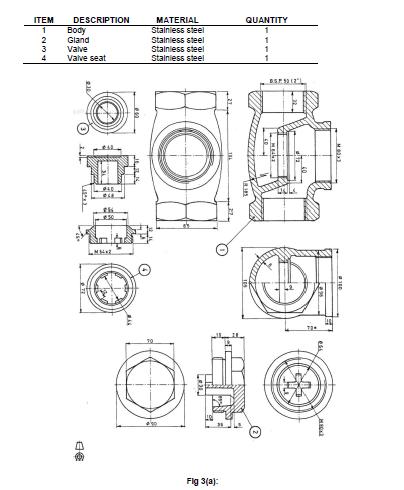
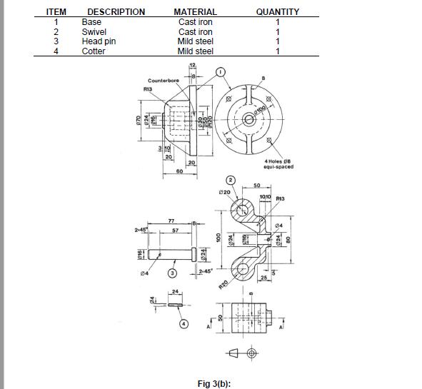
Figures 3(a) and (b) show dismantled parts of a check vale and a swivel and base, respectively. Draw the following for each assembly: (a) A full sectional front view of each assembly on separate sheets or sheet sides ( you are allowed to use both sides) (b) Add a projection symbol, part list, title and part numbers (these will always count towards the final mark) ITEM DESCRIPTION MATERIAL QUANTITY Stalniess steel Body Gland Valve Valve seat Stalnless steel Stainiess steel Stainiess steel 3 4 LMH Fig 3(a): L ITEM DESCRIPTION Base Swivel MATERIAL QUANTITY 1 Cast iron 1 2 3 Head pin Cotter Cast iron Mild steel 1 1 4 Mild steel 1 Counterbore R13 100 3 ho 20 80 4 Holes D8 equi-spaced 50 020 1010 R13 77 2-45 57 04 04 R20 Fig 3(b): 24
Step by Step Solution
3.33 Rating (156 Votes )
There are 3 Steps involved in it
or Sectiona... View full answer

Get step-by-step solutions from verified subject matter experts