

Question: TITLE: To check alignment of Lathe machine using dial gauge. OBJECTIVE: APPARATUS: After studying this experiment, you should be able to: 1. Understand the


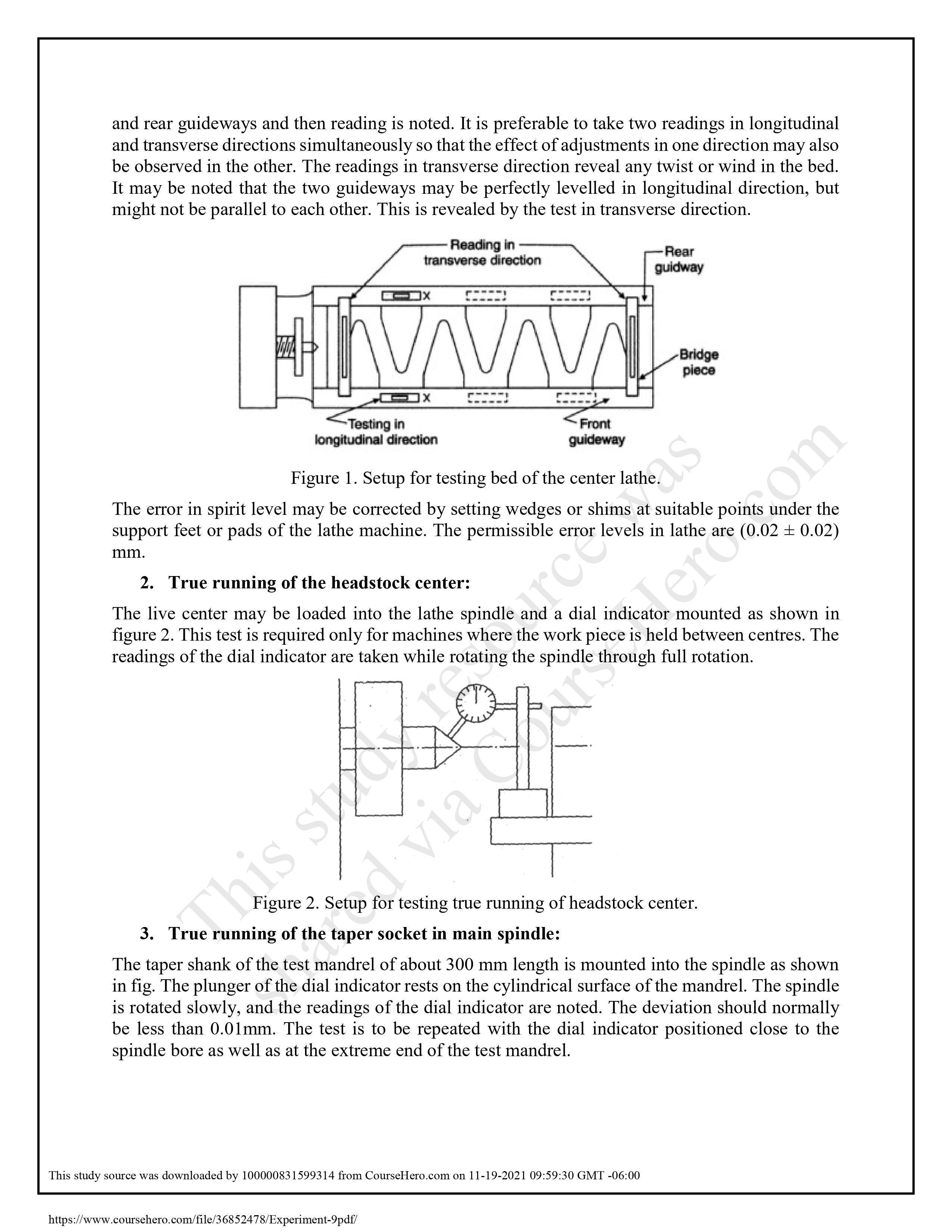

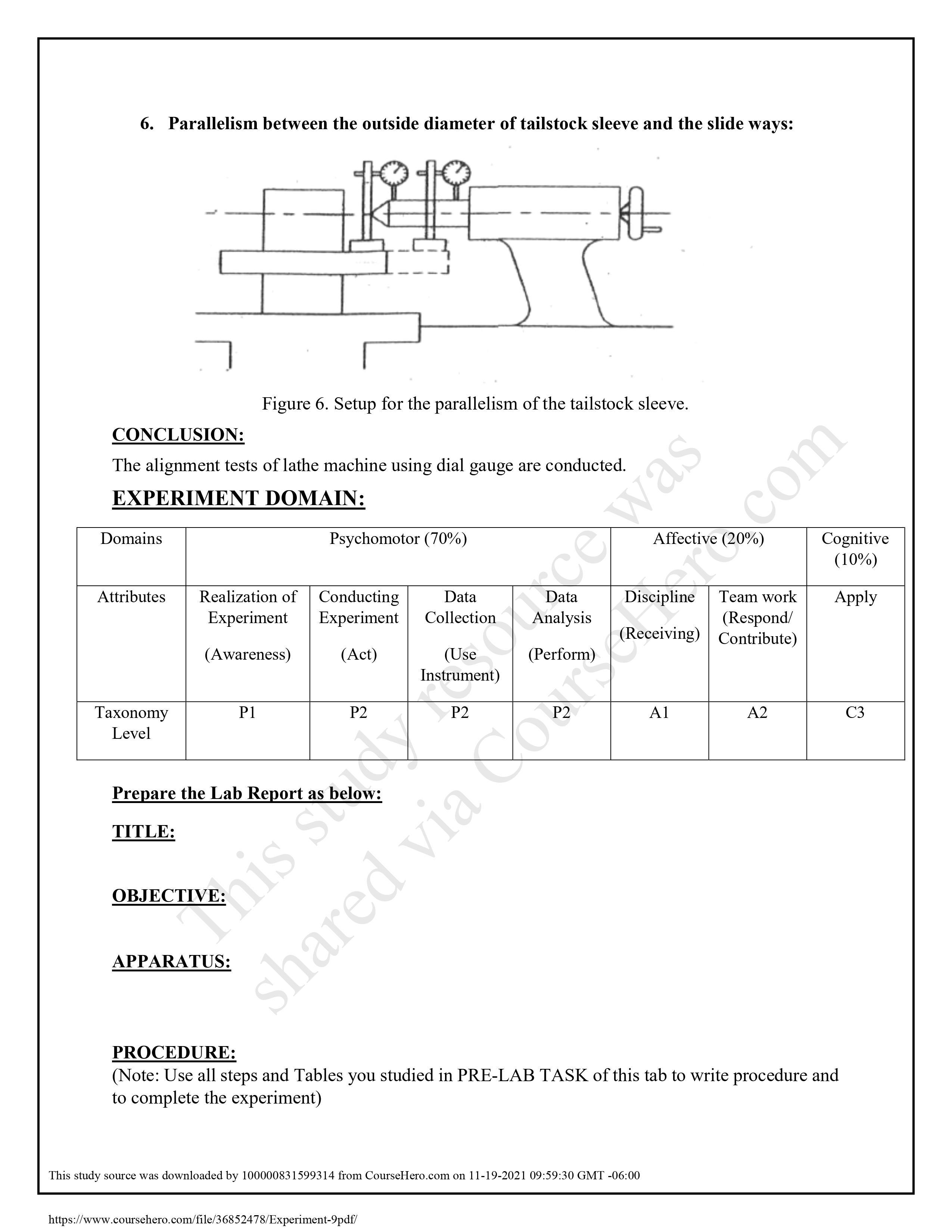


TITLE: To check alignment of Lathe machine using dial gauge. OBJECTIVE: APPARATUS: After studying this experiment, you should be able to: 1. Understand the importance of machine tools alignment tests. 2. How to conduct alignment tests on lathe machine Dial Indicators Test mandrels Straight edges Spirit levels THEORY; LATHE MACHINE ALIGNMENT TEST. 1. Geometrical tests 2. Practical tests. ii. iii. EXPERIMENT 09 IMPORTANCE OF MACHINE TOOL ALLIGNMENT TESTS: The surface components produced by machining processes are mostly by generation. As a result, the quality of surface produced depends upon the accuracy of the various movements of the machine tool concerned. It therefore becomes important to know the capability of the machine tool by evaluating the accuracy of the various mechanisms that are directly responsible for generating the surface. For this purpose, a large variety of tests have been designed. TYPES OF MACHINE TOOL ALLIGNMENT TESTS: These tests can be categorized in following categories. s stu al tests: 1. Geometrical are c These tests are check on the relationship of the various elements of the machine when it is idle and unloaded and are performed by using ordinary measuring equipment together with a few special accessories. The various i. Straightness: . Sometric checks generally made on the machine tools are: d via ce was Hero.com Straightness of a line in two planes Straightness of slideways of machine tools Straight-line motion Flatness: Parallelism, equidistance and coincidence: Parallelism of lines and planes https://www.coursehero.com/file/36852478/Experiment-9pdf/ This study source was downloaded by 100000831599314 from CourseHero.com on 11-19-2021 09:59:30 GMT -06:00 iv. V. vi. Parallel motion Rectilinear movements or squareness of straight lines and planes: Rotations: i. ii. iii. iv. Out of round Ecentricity Radial throw of an axis at a given point Out of true running (run out) Camming Periodical axis slip Movement of all working components: 2. Practical tests: These tests are intended to check the accuracy of the work done on the machine and are performed by machining suitable pieces and measuring these pieces. These are commonly known as "Alignment tests". INSTRUMENTS REQUIRED FOR ALLIGNMENT TESTS: The accuracy of the machine tools employed should be higher than the accuracy of the components that it produces. Similarly, the quality of the measuring equipment used for machine tool testing should be commensurate with the quality expected from such testing. A few commonly used equipment required to conduct alignment tests are following: i. ii. iii. iv. Dial gauge Test mandrels Straight edges Spirit level Autocollimator V. vi. Waviness meter. ALLIGNMENT TESTS ON LATHE: The following tests are conducted on lathe machine: Leveling of the machine True running of the headstock center cale True running of the taper socket in main spindle Parallelism of spindle axes and Bed. V. Parallelism between the line of center and slide ways. vi. Parallelism between the outside diameter of tailstock sleeve and the slide PROCEDURE OF ALLIGNMENT TESTS ON LATHE MACHINE: 1. Leveling of the machine: The level of the machine bed in longitudinal and transverse directions is generally tested by a sensitive spirit level. The saddle is kept approximately in the center of the bed support feet. The spirit level is then placed at X-X as shown in Figure 1, the ensure the level in the longitudinal direction. It is then traversed along the length of bed and readings at various places noted down. For test in transverse direction the level is placed on a bridge piece to span the front ways: and rear guideways and then reading is noted. It is preferable to take two readings in longitudinal and transverse directions simultaneously so that the effect of adjustments in one direction may also be observed in the other. The readings in transverse direction reveal any twist or wind in the bed. It may be noted that the two guideways may be perfectly levelled in longitudinal direction, but might not be parallel to each other. This is revealed by the test in transverse direction. Reading in transverse direction LINAVAVA -Testing in longitudinal direction Figure 1. Setup for testing bed of the center lathe. Front guideway This sho The error in spirit level may be corrected by setting wedges or shims at suitable points under the support feet or pads of the lathe machine. The permissible error levels in lathe are (0.02 0.02) mm. merce refplan! https://www.coursehero.com/file/36852478/Experiment-9pdf/ 2. True running of the headstock center: The live center may be loaded into the lathe spindle and a dial indicator mounted as shown in figure 2. This test is required only for machines where the work piece is held between centres. The readings of the dial indicator are taken while rotating the spindle through full rotation. -Rear guidway divia Cr M Bridge piece has This study source was downloaded by 100000831599314 from CourseHero.com on 11-19-2021 09:59:30 GMT -06:00 om Figure 2. Setup for testing true running of headstock center. 3. True running of the taper socket in main spindle: The taper shank of the test mandrel of about 300 mm length is mounted into the spindle as shown in fig. The plunger of the dial indicator rests on the cylindrical surface of the mandrel. The spindle is rotated slowly, and the readings of the dial indicator are noted. The deviation should normally be less than 0.01mm. The test is to be repeated with the dial indicator positioned close to the spindle bore as well as at the extreme end of the test mandrel. ere Dial indicator Figure 3. Setup for testing true running of taper socket in main spindle. 4. Parallelism of spindle axes and bed: Parallelism and perpendicularity between two axes or two surfaces is normally measured in two planes, horizontal and vertical. For this purpose, the test mandrel is mounted in the spindle as shown in figure 3 with dial indicator mounted on the saddle or carriage. The plunger of the dial indicator touches the mandrel surface as shown in fig. the saddle is moved for a specified distance and the dial reading noted. The test is repeated in the horizontal direction as well. S ++ Head stock Mandrel Carriage Figure 4. Setup for testing parallelism between the spindle axis and slideways in lathe. 5. Parallelism between the line of center and slide ways: centertwee This test is to be carried out in vertical plane only. A mandrel is fitted between the two centers and dial gauge on saddle or carriage. The plunger of dial gauge is pressed against the mandrel in vertical plane as shown in figure 4 and carriage is moved and the error recorded. Dial gauge- (b) Nource https://www.coursehero.com/file/36852478/Experiment-9pdf/ Mandrel -Lathe bed seHero. Tailstock Figure 5. Setup for testing alignment of both centers in vertical plane. This study source was downloaded by 100000831599314 from CourseHero.com on 11-19-2021 09:59:30 GMT -06:00 6. Parallelism between the outside diameter of tailstock sleeve and the slide ways: Domains CONCLUSION: The alignment tests of lathe machine using dial gauge are conducted. EXPERIMENT DOMAIN: Attributes Taxonomy Level TITLE: Realization of Conducting Data Experiment Experiment Collection (Awareness) OBJECTIVE: Figure 6. Setup for the parallelism of the tailstock sleeve. P1 Psychomotor (70%) APPARATUS: Prepare the Lab Report as below: (Act) his s P2 (Use Instrument) VANAS SIUN P2 https://www.coursehero.com/file/36852478/Experiment-9pdf/ t shared via Analysis (Perform) ce was Discipline Team work (Respond/ (Receiving) Contribute) This study source was downloaded by 100000831599314 from CourseHero.com on 11-19-2021 09:59:30 GMT -06:00 com A1 A2 PROCEDURE: (Note: Use all steps and Tables you studied in PRE-LAB TASK of this tab to write procedure and to complete the experiment) Cognitive (10%) Apply C3 RESULTS: DISCUSSION: What is the purpose of locating cylinder in the test of the true running of the main spindle? In leveling of machine, which direction is more important in horizontal plane? How you calculate graduation or least count of the dial gauge? Why are the alignment tests of lathe machine important? . COMMENTS: ********** TITLE: To check alignment of Lathe machine using dial gauge. OBJECTIVE: APPARATUS: After studying this experiment, you should be able to: 1. Understand the importance of machine tools alignment tests. 2. How to conduct alignment tests on lathe machine Dial Indicators Test mandrels Straight edges Spirit levels THEORY; LATHE MACHINE ALIGNMENT TEST. 1. Geometrical tests 2. Practical tests. ii. iii. EXPERIMENT 09 IMPORTANCE OF MACHINE TOOL ALLIGNMENT TESTS: The surface components produced by machining processes are mostly by generation. As a result, the quality of surface produced depends upon the accuracy of the various movements of the machine tool concerned. It therefore becomes important to know the capability of the machine tool by evaluating the accuracy of the various mechanisms that are directly responsible for generating the surface. For this purpose, a large variety of tests have been designed. TYPES OF MACHINE TOOL ALLIGNMENT TESTS: These tests can be categorized in following categories. s stu al tests: 1. Geometrical are c These tests are check on the relationship of the various elements of the machine when it is idle and unloaded and are performed by using ordinary measuring equipment together with a few special accessories. The various i. Straightness: . Sometric checks generally made on the machine tools are: d via ce was Hero.com Straightness of a line in two planes Straightness of slideways of machine tools Straight-line motion Flatness: Parallelism, equidistance and coincidence: Parallelism of lines and planes https://www.coursehero.com/file/36852478/Experiment-9pdf/ This study source was downloaded by 100000831599314 from CourseHero.com on 11-19-2021 09:59:30 GMT -06:00 iv. V. vi. Parallel motion Rectilinear movements or squareness of straight lines and planes: Rotations: i. ii. iii. iv. Out of round Ecentricity Radial throw of an axis at a given point Out of true running (run out) Camming Periodical axis slip Movement of all working components: 2. Practical tests: These tests are intended to check the accuracy of the work done on the machine and are performed by machining suitable pieces and measuring these pieces. These are commonly known as "Alignment tests". INSTRUMENTS REQUIRED FOR ALLIGNMENT TESTS: The accuracy of the machine tools employed should be higher than the accuracy of the components that it produces. Similarly, the quality of the measuring equipment used for machine tool testing should be commensurate with the quality expected from such testing. A few commonly used equipment required to conduct alignment tests are following: i. ii. iii. iv. Dial gauge Test mandrels Straight edges Spirit level Autocollimator V. vi. Waviness meter. ALLIGNMENT TESTS ON LATHE: The following tests are conducted on lathe machine: Leveling of the machine True running of the headstock center cale True running of the taper socket in main spindle Parallelism of spindle axes and Bed. V. Parallelism between the line of center and slide ways. vi. Parallelism between the outside diameter of tailstock sleeve and the slide PROCEDURE OF ALLIGNMENT TESTS ON LATHE MACHINE: 1. Leveling of the machine: The level of the machine bed in longitudinal and transverse directions is generally tested by a sensitive spirit level. The saddle is kept approximately in the center of the bed support feet. The spirit level is then placed at X-X as shown in Figure 1, the ensure the level in the longitudinal direction. It is then traversed along the length of bed and readings at various places noted down. For test in transverse direction the level is placed on a bridge piece to span the front ways: and rear guideways and then reading is noted. It is preferable to take two readings in longitudinal and transverse directions simultaneously so that the effect of adjustments in one direction may also be observed in the other. The readings in transverse direction reveal any twist or wind in the bed. It may be noted that the two guideways may be perfectly levelled in longitudinal direction, but might not be parallel to each other. This is revealed by the test in transverse direction. Reading in transverse direction LINAVAVA -Testing in longitudinal direction Figure 1. Setup for testing bed of the center lathe. Front guideway This sho The error in spirit level may be corrected by setting wedges or shims at suitable points under the support feet or pads of the lathe machine. The permissible error levels in lathe are (0.02 0.02) mm. merce refplan! https://www.coursehero.com/file/36852478/Experiment-9pdf/ 2. True running of the headstock center: The live center may be loaded into the lathe spindle and a dial indicator mounted as shown in figure 2. This test is required only for machines where the work piece is held between centres. The readings of the dial indicator are taken while rotating the spindle through full rotation. -Rear guidway divia Cr M Bridge piece has This study source was downloaded by 100000831599314 from CourseHero.com on 11-19-2021 09:59:30 GMT -06:00 om Figure 2. Setup for testing true running of headstock center. 3. True running of the taper socket in main spindle: The taper shank of the test mandrel of about 300 mm length is mounted into the spindle as shown in fig. The plunger of the dial indicator rests on the cylindrical surface of the mandrel. The spindle is rotated slowly, and the readings of the dial indicator are noted. The deviation should normally be less than 0.01mm. The test is to be repeated with the dial indicator positioned close to the spindle bore as well as at the extreme end of the test mandrel. ere Dial indicator Figure 3. Setup for testing true running of taper socket in main spindle. 4. Parallelism of spindle axes and bed: Parallelism and perpendicularity between two axes or two surfaces is normally measured in two planes, horizontal and vertical. For this purpose, the test mandrel is mounted in the spindle as shown in figure 3 with dial indicator mounted on the saddle or carriage. The plunger of the dial indicator touches the mandrel surface as shown in fig. the saddle is moved for a specified distance and the dial reading noted. The test is repeated in the horizontal direction as well. S ++ Head stock Mandrel Carriage Figure 4. Setup for testing parallelism between the spindle axis and slideways in lathe. 5. Parallelism between the line of center and slide ways: centertwee This test is to be carried out in vertical plane only. A mandrel is fitted between the two centers and dial gauge on saddle or carriage. The plunger of dial gauge is pressed against the mandrel in vertical plane as shown in figure 4 and carriage is moved and the error recorded. Dial gauge- (b) Nource https://www.coursehero.com/file/36852478/Experiment-9pdf/ Mandrel -Lathe bed seHero. Tailstock Figure 5. Setup for testing alignment of both centers in vertical plane. This study source was downloaded by 100000831599314 from CourseHero.com on 11-19-2021 09:59:30 GMT -06:00 6. Parallelism between the outside diameter of tailstock sleeve and the slide ways: Domains CONCLUSION: The alignment tests of lathe machine using dial gauge are conducted. EXPERIMENT DOMAIN: Attributes Taxonomy Level TITLE: Realization of Conducting Data Experiment Experiment Collection (Awareness) OBJECTIVE: Figure 6. Setup for the parallelism of the tailstock sleeve. P1 Psychomotor (70%) APPARATUS: Prepare the Lab Report as below: (Act) his s P2 (Use Instrument) VANAS SIUN P2 https://www.coursehero.com/file/36852478/Experiment-9pdf/ t shared via Analysis (Perform) ce was Discipline Team work (Respond/ (Receiving) Contribute) This study source was downloaded by 100000831599314 from CourseHero.com on 11-19-2021 09:59:30 GMT -06:00 com A1 A2 PROCEDURE: (Note: Use all steps and Tables you studied in PRE-LAB TASK of this tab to write procedure and to complete the experiment) Cognitive (10%) Apply C3 RESULTS: DISCUSSION: What is the purpose of locating cylinder in the test of the true running of the main spindle? In leveling of machine, which direction is more important in horizontal plane? How you calculate graduation or least count of the dial gauge? Why are the alignment tests of lathe machine important? . COMMENTS: ********** TITLE: To check alignment of Lathe machine using dial gauge. OBJECTIVE: APPARATUS: After studying this experiment, you should be able to: 1. Understand the importance of machine tools alignment tests. 2. How to conduct alignment tests on lathe machine Dial Indicators Test mandrels Straight edges Spirit levels THEORY; LATHE MACHINE ALIGNMENT TEST. 1. Geometrical tests 2. Practical tests. ii. iii. EXPERIMENT 09 IMPORTANCE OF MACHINE TOOL ALLIGNMENT TESTS: The surface components produced by machining processes are mostly by generation. As a result, the quality of surface produced depends upon the accuracy of the various movements of the machine tool concerned. It therefore becomes important to know the capability of the machine tool by evaluating the accuracy of the various mechanisms that are directly responsible for generating the surface. For this purpose, a large variety of tests have been designed. TYPES OF MACHINE TOOL ALLIGNMENT TESTS: These tests can be categorized in following categories. s stu al tests: 1. Geometrical are c These tests are check on the relationship of the various elements of the machine when it is idle and unloaded and are performed by using ordinary measuring equipment together with a few special accessories. The various i. Straightness: . Sometric checks generally made on the machine tools are: d via ce was Hero.com Straightness of a line in two planes Straightness of slideways of machine tools Straight-line motion Flatness: Parallelism, equidistance and coincidence: Parallelism of lines and planes https://www.coursehero.com/file/36852478/Experiment-9pdf/ This study source was downloaded by 100000831599314 from CourseHero.com on 11-19-2021 09:59:30 GMT -06:00 iv. V. vi. Parallel motion Rectilinear movements or squareness of straight lines and planes: Rotations: i. ii. iii. iv. Out of round Ecentricity Radial throw of an axis at a given point Out of true running (run out) Camming Periodical axis slip Movement of all working components: 2. Practical tests: These tests are intended to check the accuracy of the work done on the machine and are performed by machining suitable pieces and measuring these pieces. These are commonly known as "Alignment tests". INSTRUMENTS REQUIRED FOR ALLIGNMENT TESTS: The accuracy of the machine tools employed should be higher than the accuracy of the components that it produces. Similarly, the quality of the measuring equipment used for machine tool testing should be commensurate with the quality expected from such testing. A few commonly used equipment required to conduct alignment tests are following: i. ii. iii. iv. Dial gauge Test mandrels Straight edges Spirit level Autocollimator V. vi. Waviness meter. ALLIGNMENT TESTS ON LATHE: The following tests are conducted on lathe machine: Leveling of the machine True running of the headstock center cale True running of the taper socket in main spindle Parallelism of spindle axes and Bed. V. Parallelism between the line of center and slide ways. vi. Parallelism between the outside diameter of tailstock sleeve and the slide PROCEDURE OF ALLIGNMENT TESTS ON LATHE MACHINE: 1. Leveling of the machine: The level of the machine bed in longitudinal and transverse directions is generally tested by a sensitive spirit level. The saddle is kept approximately in the center of the bed support feet. The spirit level is then placed at X-X as shown in Figure 1, the ensure the level in the longitudinal direction. It is then traversed along the length of bed and readings at various places noted down. For test in transverse direction the level is placed on a bridge piece to span the front ways: and rear guideways and then reading is noted. It is preferable to take two readings in longitudinal and transverse directions simultaneously so that the effect of adjustments in one direction may also be observed in the other. The readings in transverse direction reveal any twist or wind in the bed. It may be noted that the two guideways may be perfectly levelled in longitudinal direction, but might not be parallel to each other. This is revealed by the test in transverse direction. Reading in transverse direction LINAVAVA -Testing in longitudinal direction Figure 1. Setup for testing bed of the center lathe. Front guideway This sho The error in spirit level may be corrected by setting wedges or shims at suitable points under the support feet or pads of the lathe machine. The permissible error levels in lathe are (0.02 0.02) mm. merce refplan! https://www.coursehero.com/file/36852478/Experiment-9pdf/ 2. True running of the headstock center: The live center may be loaded into the lathe spindle and a dial indicator mounted as shown in figure 2. This test is required only for machines where the work piece is held between centres. The readings of the dial indicator are taken while rotating the spindle through full rotation. -Rear guidway divia Cr M Bridge piece has This study source was downloaded by 100000831599314 from CourseHero.com on 11-19-2021 09:59:30 GMT -06:00 om Figure 2. Setup for testing true running of headstock center. 3. True running of the taper socket in main spindle: The taper shank of the test mandrel of about 300 mm length is mounted into the spindle as shown in fig. The plunger of the dial indicator rests on the cylindrical surface of the mandrel. The spindle is rotated slowly, and the readings of the dial indicator are noted. The deviation should normally be less than 0.01mm. The test is to be repeated with the dial indicator positioned close to the spindle bore as well as at the extreme end of the test mandrel. ere Dial indicator Figure 3. Setup for testing true running of taper socket in main spindle. 4. Parallelism of spindle axes and bed: Parallelism and perpendicularity between two axes or two surfaces is normally measured in two planes, horizontal and vertical. For this purpose, the test mandrel is mounted in the spindle as shown in figure 3 with dial indicator mounted on the saddle or carriage. The plunger of the dial indicator touches the mandrel surface as shown in fig. the saddle is moved for a specified distance and the dial reading noted. The test is repeated in the horizontal direction as well. S ++ Head stock Mandrel Carriage Figure 4. Setup for testing parallelism between the spindle axis and slideways in lathe. 5. Parallelism between the line of center and slide ways: centertwee This test is to be carried out in vertical plane only. A mandrel is fitted between the two centers and dial gauge on saddle or carriage. The plunger of dial gauge is pressed against the mandrel in vertical plane as shown in figure 4 and carriage is moved and the error recorded. Dial gauge- (b) Nource https://www.coursehero.com/file/36852478/Experiment-9pdf/ Mandrel -Lathe bed seHero. Tailstock Figure 5. Setup for testing alignment of both centers in vertical plane. This study source was downloaded by 100000831599314 from CourseHero.com on 11-19-2021 09:59:30 GMT -06:00 6. Parallelism between the outside diameter of tailstock sleeve and the slide ways: Domains CONCLUSION: The alignment tests of lathe machine using dial gauge are conducted. EXPERIMENT DOMAIN: Attributes Taxonomy Level TITLE: Realization of Conducting Data Experiment Experiment Collection (Awareness) OBJECTIVE: Figure 6. Setup for the parallelism of the tailstock sleeve. P1 Psychomotor (70%) APPARATUS: Prepare the Lab Report as below: (Act) his s P2 (Use Instrument) VANAS SIUN P2 https://www.coursehero.com/file/36852478/Experiment-9pdf/ t shared via Analysis (Perform) ce was Discipline Team work (Respond/ (Receiving) Contribute) This study source was downloaded by 100000831599314 from CourseHero.com on 11-19-2021 09:59:30 GMT -06:00 com A1 A2 PROCEDURE: (Note: Use all steps and Tables you studied in PRE-LAB TASK of this tab to write procedure and to complete the experiment) Cognitive (10%) Apply C3 RESULTS: DISCUSSION: What is the purpose of locating cylinder in the test of the true running of the main spindle? In leveling of machine, which direction is more important in horizontal plane? How you calculate graduation or least count of the dial gauge? Why are the alignment tests of lathe machine important? . COMMENTS: ********** TITLE: To check alignment of Lathe machine using dial gauge. OBJECTIVE: APPARATUS: After studying this experiment, you should be able to: 1. Understand the importance of machine tools alignment tests. 2. How to conduct alignment tests on lathe machine Dial Indicators Test mandrels Straight edges Spirit levels THEORY; LATHE MACHINE ALIGNMENT TEST. 1. Geometrical tests 2. Practical tests. ii. iii. EXPERIMENT 09 IMPORTANCE OF MACHINE TOOL ALLIGNMENT TESTS: The surface components produced by machining processes are mostly by generation. As a result, the quality of surface produced depends upon the accuracy of the various movements of the machine tool concerned. It therefore becomes important to know the capability of the machine tool by evaluating the accuracy of the various mechanisms that are directly responsible for generating the surface. For this purpose, a large variety of tests have been designed. TYPES OF MACHINE TOOL ALLIGNMENT TESTS: These tests can be categorized in following categories. s stu al tests: 1. Geometrical are c These tests are check on the relationship of the various elements of the machine when it is idle and unloaded and are performed by using ordinary measuring equipment together with a few special accessories. The various i. Straightness: . Sometric checks generally made on the machine tools are: d via ce was Hero.com Straightness of a line in two planes Straightness of slideways of machine tools Straight-line motion Flatness: Parallelism, equidistance and coincidence: Parallelism of lines and planes https://www.coursehero.com/file/36852478/Experiment-9pdf/ This study source was downloaded by 100000831599314 from CourseHero.com on 11-19-2021 09:59:30 GMT -06:00 iv. V. vi. Parallel motion Rectilinear movements or squareness of straight lines and planes: Rotations: i. ii. iii. iv. Out of round Ecentricity Radial throw of an axis at a given point Out of true running (run out) Camming Periodical axis slip Movement of all working components: 2. Practical tests: These tests are intended to check the accuracy of the work done on the machine and are performed by machining suitable pieces and measuring these pieces. These are commonly known as "Alignment tests". INSTRUMENTS REQUIRED FOR ALLIGNMENT TESTS: The accuracy of the machine tools employed should be higher than the accuracy of the components that it produces. Similarly, the quality of the measuring equipment used for machine tool testing should be commensurate with the quality expected from such testing. A few commonly used equipment required to conduct alignment tests are following: i. ii. iii. iv. Dial gauge Test mandrels Straight edges Spirit level Autocollimator V. vi. Waviness meter. ALLIGNMENT TESTS ON LATHE: The following tests are conducted on lathe machine: Leveling of the machine True running of the headstock center cale True running of the taper socket in main spindle Parallelism of spindle axes and Bed. V. Parallelism between the line of center and slide ways. vi. Parallelism between the outside diameter of tailstock sleeve and the slide PROCEDURE OF ALLIGNMENT TESTS ON LATHE MACHINE: 1. Leveling of the machine: The level of the machine bed in longitudinal and transverse directions is generally tested by a sensitive spirit level. The saddle is kept approximately in the center of the bed support feet. The spirit level is then placed at X-X as shown in Figure 1, the ensure the level in the longitudinal direction. It is then traversed along the length of bed and readings at various places noted down. For test in transverse direction the level is placed on a bridge piece to span the front ways: and rear guideways and then reading is noted. It is preferable to take two readings in longitudinal and transverse directions simultaneously so that the effect of adjustments in one direction may also be observed in the other. The readings in transverse direction reveal any twist or wind in the bed. It may be noted that the two guideways may be perfectly levelled in longitudinal direction, but might not be parallel to each other. This is revealed by the test in transverse direction. Reading in transverse direction LINAVAVA -Testing in longitudinal direction Figure 1. Setup for testing bed of the center lathe. Front guideway This sho The error in spirit level may be corrected by setting wedges or shims at suitable points under the support feet or pads of the lathe machine. The permissible error levels in lathe are (0.02 0.02) mm. merce refplan! https://www.coursehero.com/file/36852478/Experiment-9pdf/ 2. True running of the headstock center: The live center may be loaded into the lathe spindle and a dial indicator mounted as shown in figure 2. This test is required only for machines where the work piece is held between centres. The readings of the dial indicator are taken while rotating the spindle through full rotation. -Rear guidway divia Cr M Bridge piece has This study source was downloaded by 100000831599314 from CourseHero.com on 11-19-2021 09:59:30 GMT -06:00 om Figure 2. Setup for testing true running of headstock center. 3. True running of the taper socket in main spindle: The taper shank of the test mandrel of about 300 mm length is mounted into the spindle as shown in fig. The plunger of the dial indicator rests on the cylindrical surface of the mandrel. The spindle is rotated slowly, and the readings of the dial indicator are noted. The deviation should normally be less than 0.01mm. The test is to be repeated with the dial indicator positioned close to the spindle bore as well as at the extreme end of the test mandrel. ere Dial indicator Figure 3. Setup for testing true running of taper socket in main spindle. 4. Parallelism of spindle axes and bed: Parallelism and perpendicularity between two axes or two surfaces is normally measured in two planes, horizontal and vertical. For this purpose, the test mandrel is mounted in the spindle as shown in figure 3 with dial indicator mounted on the saddle or carriage. The plunger of the dial indicator touches the mandrel surface as shown in fig. the saddle is moved for a specified distance and the dial reading noted. The test is repeated in the horizontal direction as well. S ++ Head stock Mandrel Carriage Figure 4. Setup for testing parallelism between the spindle axis and slideways in lathe. 5. Parallelism between the line of center and slide ways: centertwee This test is to be carried out in vertical plane only. A mandrel is fitted between the two centers and dial gauge on saddle or carriage. The plunger of dial gauge is pressed against the mandrel in vertical plane as shown in figure 4 and carriage is moved and the error recorded. Dial gauge- (b) Nource https://www.coursehero.com/file/36852478/Experiment-9pdf/ Mandrel -Lathe bed seHero. Tailstock Figure 5. Setup for testing alignment of both centers in vertical plane. This study source was downloaded by 100000831599314 from CourseHero.com on 11-19-2021 09:59:30 GMT -06:00 6. Parallelism between the outside diameter of tailstock sleeve and the slide ways: Domains CONCLUSION: The alignment tests of lathe machine using dial gauge are conducted. EXPERIMENT DOMAIN: Attributes Taxonomy Level TITLE: Realization of Conducting Data Experiment Experiment Collection (Awareness) OBJECTIVE: Figure 6. Setup for the parallelism of the tailstock sleeve. P1 Psychomotor (70%) APPARATUS: Prepare the Lab Report as below: (Act) his s P2 (Use Instrument) VANAS SIUN P2 https://www.coursehero.com/file/36852478/Experiment-9pdf/ t shared via Analysis (Perform) ce was Discipline Team work (Respond/ (Receiving) Contribute) This study source was downloaded by 100000831599314 from CourseHero.com on 11-19-2021 09:59:30 GMT -06:00 com A1 A2 PROCEDURE: (Note: Use all steps and Tables you studied in PRE-LAB TASK of this tab to write procedure and to complete the experiment) Cognitive (10%) Apply C3 RESULTS: DISCUSSION: What is the purpose of locating cylinder in the test of the true running of the main spindle? In leveling of machine, which direction is more important in horizontal plane? How you calculate graduation or least count of the dial gauge? Why are the alignment tests of lathe machine important? . COMMENTS: ********** TITLE: To check alignment of Lathe machine using dial gauge. OBJECTIVE: APPARATUS: After studying this experiment, you should be able to: 1. Understand the importance of machine tools alignment tests. 2. How to conduct alignment tests on lathe machine Dial Indicators Test mandrels Straight edges Spirit levels THEORY; LATHE MACHINE ALIGNMENT TEST. 1. Geometrical tests 2. Practical tests. ii. iii. EXPERIMENT 09 IMPORTANCE OF MACHINE TOOL ALLIGNMENT TESTS: The surface components produced by machining processes are mostly by generation. As a result, the quality of surface produced depends upon the accuracy of the various movements of the machine tool concerned. It therefore becomes important to know the capability of the machine tool by evaluating the accuracy of the various mechanisms that are directly responsible for generating the surface. For this purpose, a large variety of tests have been designed. TYPES OF MACHINE TOOL ALLIGNMENT TESTS: These tests can be categorized in following categories. s stu al tests: 1. Geometrical are c These tests are check on the relationship of the various elements of the machine when it is idle and unloaded and are performed by using ordinary measuring equipment together with a few special accessories. The various i. Straightness: . Sometric checks generally made on the machine tools are: d via ce was Hero.com Straightness of a line in two planes Straightness of slideways of machine tools Straight-line motion Flatness: Parallelism, equidistance and coincidence: Parallelism of lines and planes https://www.coursehero.com/file/36852478/Experiment-9pdf/ This study source was downloaded by 100000831599314 from CourseHero.com on 11-19-2021 09:59:30 GMT -06:00 iv. V. vi. Parallel motion Rectilinear movements or squareness of straight lines and planes: Rotations: i. ii. iii. iv. Out of round Ecentricity Radial throw of an axis at a given point Out of true running (run out) Camming Periodical axis slip Movement of all working components: 2. Practical tests: These tests are intended to check the accuracy of the work done on the machine and are performed by machining suitable pieces and measuring these pieces. These are commonly known as "Alignment tests". INSTRUMENTS REQUIRED FOR ALLIGNMENT TESTS: The accuracy of the machine tools employed should be higher than the accuracy of the components that it produces. Similarly, the quality of the measuring equipment used for machine tool testing should be commensurate with the quality expected from such testing. A few commonly used equipment required to conduct alignment tests are following: i. ii. iii. iv. Dial gauge Test mandrels Straight edges Spirit level Autocollimator V. vi. Waviness meter. ALLIGNMENT TESTS ON LATHE: The following tests are conducted on lathe machine: Leveling of the machine True running of the headstock center cale True running of the taper socket in main spindle Parallelism of spindle axes and Bed. V. Parallelism between the line of center and slide ways. vi. Parallelism between the outside diameter of tailstock sleeve and the slide PROCEDURE OF ALLIGNMENT TESTS ON LATHE MACHINE: 1. Leveling of the machine: The level of the machine bed in longitudinal and transverse directions is generally tested by a sensitive spirit level. The saddle is kept approximately in the center of the bed support feet. The spirit level is then placed at X-X as shown in Figure 1, the ensure the level in the longitudinal direction. It is then traversed along the length of bed and readings at various places noted down. For test in transverse direction the level is placed on a bridge piece to span the front ways: and rear guideways and then reading is noted. It is preferable to take two readings in longitudinal and transverse directions simultaneously so that the effect of adjustments in one direction may also be observed in the other. The readings in transverse direction reveal any twist or wind in the bed. It may be noted that the two guideways may be perfectly levelled in longitudinal direction, but might not be parallel to each other. This is revealed by the test in transverse direction. Reading in transverse direction LINAVAVA -Testing in longitudinal direction Figure 1. Setup for testing bed of the center lathe. Front guideway This sho The error in spirit level may be corrected by setting wedges or shims at suitable points under the support feet or pads of the lathe machine. The permissible error levels in lathe are (0.02 0.02) mm. merce refplan! https://www.coursehero.com/file/36852478/Experiment-9pdf/ 2. True running of the headstock center: The live center may be loaded into the lathe spindle and a dial indicator mounted as shown in figure 2. This test is required only for machines where the work piece is held between centres. The readings of the dial indicator are taken while rotating the spindle through full rotation. -Rear guidway divia Cr M Bridge piece has This study source was downloaded by 100000831599314 from CourseHero.com on 11-19-2021 09:59:30 GMT -06:00 om Figure 2. Setup for testing true running of headstock center. 3. True running of the taper socket in main spindle: The taper shank of the test mandrel of about 300 mm length is mounted into the spindle as shown in fig. The plunger of the dial indicator rests on the cylindrical surface of the mandrel. The spindle is rotated slowly, and the readings of the dial indicator are noted. The deviation should normally be less than 0.01mm. The test is to be repeated with the dial indicator positioned close to the spindle bore as well as at the extreme end of the test mandrel. ere Dial indicator Figure 3. Setup for testing true running of taper socket in main spindle. 4. Parallelism of spindle axes and bed: Parallelism and perpendicularity between two axes or two surfaces is normally measured in two planes, horizontal and vertical. For this purpose, the test mandrel is mounted in the spindle as shown in figure 3 with dial indicator mounted on the saddle or carriage. The plunger of the dial indicator touches the mandrel surface as shown in fig. the saddle is moved for a specified distance and the dial reading noted. The test is repeated in the horizontal direction as well. S ++ Head stock Mandrel Carriage Figure 4. Setup for testing parallelism between the spindle axis and slideways in lathe. 5. Parallelism between the line of center and slide ways: centertwee This test is to be carried out in vertical plane only. A mandrel is fitted between the two centers and dial gauge on saddle or carriage. The plunger of dial gauge is pressed against the mandrel in vertical plane as shown in figure 4 and carriage is moved and the error recorded. Dial gauge- (b) Nource https://www.coursehero.com/file/36852478/Experiment-9pdf/ Mandrel -Lathe bed seHero. Tailstock Figure 5. Setup for testing alignment of both centers in vertical plane. This study source was downloaded by 100000831599314 from CourseHero.com on 11-19-2021 09:59:30 GMT -06:00 6. Parallelism between the outside diameter of tailstock sleeve and the slide ways: Domains CONCLUSION: The alignment tests of lathe machine using dial gauge are conducted. EXPERIMENT DOMAIN: Attributes Taxonomy Level TITLE: Realization of Conducting Data Experiment Experiment Collection (Awareness) OBJECTIVE: Figure 6. Setup for the parallelism of the tailstock sleeve. P1 Psychomotor (70%) APPARATUS: Prepare the Lab Report as below: (Act) his s P2 (Use Instrument) VANAS SIUN P2 https://www.coursehero.com/file/36852478/Experiment-9pdf/ t shared via Analysis (Perform) ce was Discipline Team work (Respond/ (Receiving) Contribute) This study source was downloaded by 100000831599314 from CourseHero.com on 11-19-2021 09:59:30 GMT -06:00 com A1 A2 PROCEDURE: (Note: Use all steps and Tables you studied in PRE-LAB TASK of this tab to write procedure and to complete the experiment) Cognitive (10%) Apply C3 RESULTS: DISCUSSION: What is the purpose of locating cylinder in the test of the true running of the main spindle? In leveling of machine, which direction is more important in horizontal plane? How you calculate graduation or least count of the dial gauge? Why are the alignment tests of lathe machine important? . COMMENTS: ********** TITLE: To check alignment of Lathe machine using dial gauge. OBJECTIVE: APPARATUS: After studying this experiment, you should be able to: 1. Understand the importance of machine tools alignment tests. 2. How to conduct alignment tests on lathe machine Dial Indicators Test mandrels Straight edges Spirit levels THEORY; LATHE MACHINE ALIGNMENT TEST. 1. Geometrical tests 2. Practical tests. ii. iii. EXPERIMENT 09 IMPORTANCE OF MACHINE TOOL ALLIGNMENT TESTS: The surface components produced by machining processes are mostly by generation. As a result, the quality of surface produced depends upon the accuracy of the various movements of the machine tool concerned. It therefore becomes important to know the capability of the machine tool by evaluating the accuracy of the various mechanisms that are directly responsible for generating the surface. For this purpose, a large variety of tests have been designed. TYPES OF MACHINE TOOL ALLIGNMENT TESTS: These tests can be categorized in following categories. s stu al tests: 1. Geometrical are c These tests are check on the relationship of the various elements of the machine when it is idle and unloaded and are performed by using ordinary measuring equipment together with a few special accessories. The various i. Straightness: . Sometric checks generally made on the machine tools are: d via ce was Hero.com Straightness of a line in two planes Straightness of slideways of machine tools Straight-line motion Flatness: Parallelism, equidistance and coincidence: Parallelism of lines and planes https://www.coursehero.com/file/36852478/Experiment-9pdf/ This study source was downloaded by 100000831599314 from CourseHero.com on 11-19-2021 09:59:30 GMT -06:00 iv. V. vi. Parallel motion Rectilinear movements or squareness of straight lines and planes: Rotations: i. ii. iii. iv. Out of round Ecentricity Radial throw of an axis at a given point Out of true running (run out) Camming Periodical axis slip Movement of all working components: 2. Practical tests: These tests are intended to check the accuracy of the work done on the machine and are performed by machining suitable pieces and measuring these pieces. These are commonly known as "Alignment tests". INSTRUMENTS REQUIRED FOR ALLIGNMENT TESTS: The accuracy of the machine tools employed should be higher than the accuracy of the components that it produces. Similarly, the quality of the measuring equipment used for machine tool testing should be commensurate with the quality expected from such testing. A few commonly used equipment required to conduct alignment tests are following: i. ii. iii. iv. Dial gauge Test mandrels Straight edges Spirit level Autocollimator V. vi. Waviness meter. ALLIGNMENT TESTS ON LATHE: The following tests are conducted on lathe machine: Leveling of the machine True running of the headstock center cale True running of the taper socket in main spindle Parallelism of spindle axes and Bed. V. Parallelism between the line of center and slide ways. vi. Parallelism between the outside diameter of tailstock sleeve and the slide PROCEDURE OF ALLIGNMENT TESTS ON LATHE MACHINE: 1. Leveling of the machine: The level of the machine bed in longitudinal and transverse directions is generally tested by a sensitive spirit level. The saddle is kept approximately in the center of the bed support feet. The spirit level is then placed at X-X as shown in Figure 1, the ensure the level in the longitudinal direction. It is then traversed along the length of bed and readings at various places noted down. For test in transverse direction the level is placed on a bridge piece to span the front ways: and rear guideways and then reading is noted. It is preferable to take two readings in longitudinal and transverse directions simultaneously so that the effect of adjustments in one direction may also be observed in the other. The readings in transverse direction reveal any twist or wind in the bed. It may be noted that the two guideways may be perfectly levelled in longitudinal direction, but might not be parallel to each other. This is revealed by the test in transverse direction. Reading in transverse direction LINAVAVA -Testing in longitudinal direction Figure 1. Setup for testing bed of the center lathe. Front guideway This sho The error in spirit level may be corrected by setting wedges or shims at suitable points under the support feet or pads of the lathe machine. The permissible error levels in lathe are (0.02 0.02) mm. merce refplan! https://www.coursehero.com/file/36852478/Experiment-9pdf/ 2. True running of the headstock center: The live center may be loaded into the lathe spindle and a dial indicator mounted as shown in figure 2. This test is required only for machines where the work piece is held between centres. The readings of the dial indicator are taken while rotating the spindle through full rotation. -Rear guidway divia Cr M Bridge piece has This study source was downloaded by 100000831599314 from CourseHero.com on 11-19-2021 09:59:30 GMT -06:00 om Figure 2. Setup for testing true running of headstock center. 3. True running of the taper socket in main spindle: The taper shank of the test mandrel of about 300 mm length is mounted into the spindle as shown in fig. The plunger of the dial indicator rests on the cylindrical surface of the mandrel. The spindle is rotated slowly, and the readings of the dial indicator are noted. The deviation should normally be less than 0.01mm. The test is to be repeated with the dial indicator positioned close to the spindle bore as well as at the extreme end of the test mandrel. ere Dial indicator Figure 3. Setup for testing true running of taper socket in main spindle. 4. Parallelism of spindle axes and bed: Parallelism and perpendicularity between two axes or two surfaces is normally measured in two planes, horizontal and vertical. For this purpose, the test mandrel is mounted in the spindle as shown in figure 3 with dial indicator mounted on the saddle or carriage. The plunger of the dial indicator touches the mandrel surface as shown in fig. the saddle is moved for a specified distance and the dial reading noted. The test is repeated in the horizontal direction as well. S ++ Head stock Mandrel Carriage Figure 4. Setup for testing parallelism between the spindle axis and slideways in lathe. 5. Parallelism between the line of center and slide ways: centertwee This test is to be carried out in vertical plane only. A mandrel is fitted between the two centers and dial gauge on saddle or carriage. The plunger of dial gauge is pressed against the mandrel in vertical plane as shown in figure 4 and carriage is moved and the error recorded. Dial gauge- (b) Nource https://www.coursehero.com/file/36852478/Experiment-9pdf/ Mandrel -Lathe bed seHero. Tailstock Figure 5. Setup for testing alignment of both centers in vertical plane. This study source was downloaded by 100000831599314 from CourseHero.com on 11-19-2021 09:59:30 GMT -06:00 6. Parallelism between the outside diameter of tailstock sleeve and the slide ways: Domains CONCLUSION: The alignment tests of lathe machine using dial gauge are conducted. EXPERIMENT DOMAIN: Attributes Taxonomy Level TITLE: Realization of Conducting Data Experiment Experiment Collection (Awareness) OBJECTIVE: Figure 6. Setup for the parallelism of the tailstock sleeve. P1 Psychomotor (70%) APPARATUS: Prepare the Lab Report as below: (Act) his s P2 (Use Instrument) VANAS SIUN P2 https://www.coursehero.com/file/36852478/Experiment-9pdf/ t shared via Analysis (Perform) ce was Discipline Team work (Respond/ (Receiving) Contribute) This study source was downloaded by 100000831599314 from CourseHero.com on 11-19-2021 09:59:30 GMT -06:00 com A1 A2 PROCEDURE: (Note: Use all steps and Tables you studied in PRE-LAB TASK of this tab to write procedure and to complete the experiment) Cognitive (10%) Apply C3 RESULTS: DISCUSSION: What is the purpose of locating cylinder in the test of the true running of the main spindle? In leveling of machine, which direction is more important in horizontal plane? How you calculate graduation or least count of the dial gauge? Why are the alignment tests of lathe machine important? . COMMENTS: ********** TITLE: To check alignment of Lathe machine using dial gauge. OBJECTIVE: APPARATUS: After studying this experiment, you should be able to: 1. Understand the importance of machine tools alignment tests. 2. How to conduct alignment tests on lathe machine Dial Indicators Test mandrels Straight edges Spirit levels THEORY; LATHE MACHINE ALIGNMENT TEST. 1. Geometrical tests 2. Practical tests. ii. iii. EXPERIMENT 09 IMPORTANCE OF MACHINE TOOL ALLIGNMENT TESTS: The surface components produced by machining processes are mostly by generation. As a result, the quality of surface produced depends upon the accuracy of the various movements of the machine tool concerned. It therefore becomes important to know the capability of the machine tool by evaluating the accuracy of the various mechanisms that are directly responsible for generating the surface. For this purpose, a large variety of tests have been designed. TYPES OF MACHINE TOOL ALLIGNMENT TESTS: These tests can be categorized in following categories. s stu al tests: 1. Geometrical are c These tests are check on the relationship of the various elements of the machine when it is idle and unloaded and are performed by using ordinary measuring equipment together with a few special accessories. The various i. Straightness: . Sometric checks generally made on the machine tools are: d via ce was Hero.com Straightness of a line in two planes Straightness of slideways of machine tools Straight-line motion Flatness: Parallelism, equidistance and coincidence: Parallelism of lines and planes https://www.coursehero.com/file/36852478/Experiment-9pdf/ This study source was downloaded by 100000831599314 from CourseHero.com on 11-19-2021 09:59:30 GMT -06:00 iv. V. vi. Parallel motion Rectilinear movements or squareness of straight lines and planes: Rotations: i. ii. iii. iv. Out of round Ecentricity Radial throw of an axis at a given point Out of true running (run out) Camming Periodical axis slip Movement of all working components: 2. Practical tests: These tests are intended to check the accuracy of the work done on the machine and are performed by machining suitable pieces and measuring these pieces. These are commonly known as "Alignment tests". INSTRUMENTS REQUIRED FOR ALLIGNMENT TESTS: The accuracy of the machine tools employed should be higher than the accuracy of the components that it produces. Similarly, the quality of the measuring equipment used for machine tool testing should be commensurate with the quality expected from such testing. A few commonly used equipment required to conduct alignment tests are following: i. ii. iii. iv. Dial gauge Test mandrels Straight edges Spirit level Autocollimator V. vi. Waviness meter. ALLIGNMENT TESTS ON LATHE: The following tests are conducted on lathe machine: Leveling of the machine True running of the headstock center cale True running of the taper socket in main spindle Parallelism of spindle axes and Bed. V. Parallelism between the line of center and slide ways. vi. Parallelism between the outside diameter of tailstock sleeve and the slide PROCEDURE OF ALLIGNMENT TESTS ON LATHE MACHINE: 1. Leveling of the machine: The level of the machine bed in longitudinal and transverse directions is generally tested by a sensitive spirit level. The saddle is kept approximately in the center of the bed support feet. The spirit level is then placed at X-X as shown in Figure 1, the ensure the level in the longitudinal direction. It is then traversed along the length of bed and readings at various places noted down. For test in transverse direction the level is placed on a bridge piece to span the front ways: and rear guideways and then reading is noted. It is preferable to take two readings in longitudinal and transverse directions simultaneously so that the effect of adjustments in one direction may also be observed in the other. The readings in transverse direction reveal any twist or wind in the bed. It may be noted that the two guideways may be perfectly levelled in longitudinal direction, but might not be parallel to each other. This is revealed by the test in transverse direction. Reading in transverse direction LINAVAVA -Testing in longitudinal direction Figure 1. Setup for testing bed of the center lathe. Front guideway This sho The error in spirit level may be corrected by setting wedges or shims at suitable points under the support feet or pads of the lathe machine. The permissible error levels in lathe are (0.02 0.02) mm. merce refplan! https://www.coursehero.com/file/36852478/Experiment-9pdf/ 2. True running of the headstock center: The live center may be loaded into the lathe spindle and a dial indicator mounted as shown in figure 2. This test is required only for machines where the work piece is held between centres. The readings of the dial indicator are taken while rotating the spindle through full rotation. -Rear guidway divia Cr M Bridge piece has This study source was downloaded by 100000831599314 from CourseHero.com on 11-19-2021 09:59:30 GMT -06:00 om Figure 2. Setup for testing true running of headstock center. 3. True running of the taper socket in main spindle: The taper shank of the test mandrel of about 300 mm length is mounted into the spindle as shown in fig. The plunger of the dial indicator rests on the cylindrical surface of the mandrel. The spindle is rotated slowly, and the readings of the dial indicator are noted. The deviation should normally be less than 0.01mm. The test is to be repeated with the dial indicator positioned close to the spindle bore as well as at the extreme end of the test mandrel. ere Dial indicator Figure 3. Setup for testing true running of taper socket in main spindle. 4. Parallelism of spindle axes and bed: Parallelism and perpendicularity between two axes or two surfaces is normally measured in two planes, horizontal and vertical. For this purpose, the test mandrel is mounted in the spindle as shown in figure 3 with dial indicator mounted on the saddle or carriage. The plunger of the dial indicator touches the mandrel surface as shown in fig. the saddle is moved for a specified distance and the dial reading noted. The test is repeated in the horizontal direction as well. S ++ Head stock Mandrel Carriage Figure 4. Setup for testing parallelism between the spindle axis and slideways in lathe. 5. Parallelism between the line of center and slide ways: centertwee This test is to be carried out in vertical plane only. A mandrel is fitted between the two centers and dial gauge on saddle or carriage. The plunger of dial gauge is pressed against the mandrel in vertical plane as shown in figure 4 and carriage is moved and the error recorded. Dial gauge- (b) Nource https://www.coursehero.com/file/36852478/Experiment-9pdf/ Mandrel -Lathe bed seHero. Tailstock Figure 5. Setup for testing alignment of both centers in vertical plane. This study source was downloaded by 100000831599314 from CourseHero.com on 11-19-2021 09:59:30 GMT -06:00 6. Parallelism between the outside diameter of tailstock sleeve and the slide ways: Domains CONCLUSION: The alignment tests of lathe machine using dial gauge are conducted. EXPERIMENT DOMAIN: Attributes Taxonomy Level TITLE: Realization of Conducting Data Experiment Experiment Collection (Awareness) OBJECTIVE: Figure 6. Setup for the parallelism of the tailstock sleeve. P1 Psychomotor (70%) APPARATUS: Prepare the Lab Report as below: (Act) his s P2 (Use Instrument) VANAS SIUN P2 https://www.coursehero.com/file/36852478/Experiment-9pdf/ t shared via Analysis (Perform) ce was Discipline Team work (Respond/ (Receiving) Contribute) This study source was downloaded by 100000831599314 from CourseHero.com on 11-19-2021 09:59:30 GMT -06:00 com A1 A2 PROCEDURE: (Note: Use all steps and Tables you studied in PRE-LAB TASK of this tab to write procedure and to complete the experiment) Cognitive (10%) Apply C3 RESULTS: DISCUSSION: What is the purpose of locating cylinder in the test of the true running of the main spindle? In leveling of machine, which direction is more important in horizontal plane? How you calculate graduation or least count of the dial gauge? Why are the alignment tests of lathe machine important? . COMMENTS: ********** TITLE: To check alignment of Lathe machine using dial gauge. OBJECTIVE: APPARATUS: After studying this experiment, you should be able to: 1. Understand the importance of machine tools alignment tests. 2. How to conduct alignment tests on lathe machine Dial Indicators Test mandrels Straight edges Spirit levels THEORY; LATHE MACHINE ALIGNMENT TEST. 1. Geometrical tests 2. Practical tests. ii. iii. EXPERIMENT 09 IMPORTANCE OF MACHINE TOOL ALLIGNMENT TESTS: The surface components produced by machining processes are mostly by generation. As a result, the quality of surface produced depends upon the accuracy of the various movements of the machine tool concerned. It therefore becomes important to know the capability of the machine tool by evaluating the accuracy of the various mechanisms that are directly responsible for generating the surface. For this purpose, a large variety of tests have been designed. TYPES OF MACHINE TOOL ALLIGNMENT TESTS: These tests can be categorized in following categories. s stu al tests: 1. Geometrical are c These tests are check on the relationship of the various elements of the machine when it is idle and unloaded and are performed by using ordinary measuring equipment together with a few special accessories. The various i. Straightness: . Sometric checks generally made on the machine tools are: d via ce was Hero.com Straightness of a line in two planes Straightness of slideways of machine tools Straight-line motion Flatness: Parallelism, equidistance and coincidence: Parallelism of lines and planes https://www.coursehero.com/file/36852478/Experiment-9pdf/ This study source was downloaded by 100000831599314 from CourseHero.com on 11-19-2021 09:59:30 GMT -06:00 iv. V. vi. Parallel motion Rectilinear movements or squareness of straight lines and planes: Rotations: i. ii. iii. iv. Out of round Ecentricity Radial throw of an axis at a given point Out of true running (run out) Camming Periodical axis slip Movement of all working components: 2. Practical tests: These tests are intended to check the accuracy of the work done on the machine and are performed by machining suitable pieces and measuring these pieces. These are commonly known as "Alignment tests". INSTRUMENTS REQUIRED FOR ALLIGNMENT TESTS: The accuracy of the machine tools employed should be higher than the accuracy of the components that it produces. Similarly, the quality of the measuring equipment used for machine tool testing should be commensurate with the quality expected from such testing. A few commonly used equipment required to conduct alignment tests are following: i. ii. iii. iv. Dial gauge Test mandrels Straight edges Spirit level Autocollimator V. vi. Waviness meter. ALLIGNMENT TESTS ON LATHE: The following tests are conducted on lathe machine: Leveling of the machine True running of the headstock center cale True running of the taper socket in main spindle Parallelism of spindle axes and Bed. V. Parallelism between the line of center and slide ways. vi. Parallelism between the outside diameter of tailstock sleeve and the slide PROCEDURE OF ALLIGNMENT TESTS ON LATHE MACHINE: 1. Leveling of the machine: The level of the machine bed in longitudinal and transverse directions is generally tested by a sensitive spirit level. The saddle is kept approximately in the center of the bed support feet. The spirit level is then placed at X-X as shown in Figure 1, the ensure the level in the longitudinal direction. It is then traversed along the length of bed and readings at various places noted down. For test in transverse direction the level is placed on a bridge piece to span the front ways: and rear guideways and then reading is noted. It is preferable to take two readings in longitudinal and transverse directions simultaneously so that the effect of adjustments in one direction may also be observed in the other. The readings in transverse direction reveal any twist or wind in the bed. It may be noted that the two guideways may be perfectly levelled in longitudinal direction, but might not be parallel to each other. This is revealed by the test in transverse direction. Reading in transverse direction LINAVAVA -Testing in longitudinal direction Figure 1. Setup for testing bed of the center lathe. Front guideway This sho The error in spirit level may be corrected by setting wedges or shims at suitable points under the support feet or pads of the lathe machine. The permissible error levels in lathe are (0.02 0.02) mm. merce refplan! https://www.coursehero.com/file/36852478/Experiment-9pdf/ 2. True running of the headstock center: The live center may be loaded into the lathe spindle and a dial indicator mounted as shown in figure 2. This test is required only for machines where the work piece is held between centres. The readings of the dial indicator are taken while rotating the spindle through full rotation. -Rear guidway divia Cr M Bridge piece has This study source was downloaded by 100000831599314 from CourseHero.com on 11-19-2021 09:59:30 GMT -06:00 om Figure 2. Setup for testing true running of headstock center. 3. True running of the taper socket in main spindle: The taper shank of the test mandrel of about 300 mm length is mounted into the spindle as shown in fig. The plunger of the dial indicator rests on the cylindrical surface of the mandrel. The spindle is rotated slowly, and the readings of the dial indicator are noted. The deviation should normally be less than 0.01mm. The test is to be repeated with the dial indicator positioned close to the spindle bore as well as at the extreme end of the test mandrel. ere Dial indicator Figure 3. Setup for testing true running of taper socket in main spindle. 4. Parallelism of spindle axes and bed: Parallelism and perpendicularity between two axes or two surfaces is normally measured in two planes, horizontal and vertical. For this purpose, the test mandrel is mounted in the spindle as shown in figure 3 with dial indicator mounted on the saddle or carriage. The plunger of the dial indicator touches the mandrel surface as shown in fig. the saddle is moved for a specified distance and the dial reading noted. The test is repeated in the horizontal direction as well. S ++ Head stock Mandrel Carriage Figure 4. Setup for testing parallelism between the spindle axis and slideways in lathe. 5. Parallelism between the line of center and slide ways: centertwee This test is to be carried out in vertical plane only. A mandrel is fitted between the two centers and dial gauge on saddle or carriage. The plunger of dial gauge is pressed against the mandrel in vertical plane as shown in figure 4 and carriage is moved and the error recorded. Dial gauge- (b) Nource https://www.coursehero.com/file/36852478/Experiment-9pdf/ Mandrel -Lathe bed seHero. Tailstock Figure 5. Setup for testing alignment of both centers in vertical plane. This study source was downloaded by 100000831599314 from CourseHero.com on 11-19-2021 09:59:30 GMT -06:00 6. Parallelism between the outside diameter of tailstock sleeve and the slide ways: Domains CONCLUSION: The alignment tests of lathe machine using dial gauge are conducted. EXPERIMENT DOMAIN: Attributes Taxonomy Level TITLE: Realization of Conducting Data Experiment Experiment Collection (Awareness) OBJECTIVE: Figure 6. Setup for the parallelism of the tailstock sleeve. P1 Psychomotor (70%) APPARATUS: Prepare the Lab Report as below: (Act) his s P2 (Use Instrument) VANAS SIUN P2 https://www.coursehero.com/file/36852478/Experiment-9pdf/ t shared via Analysis (Perform) ce was Discipline Team work (Respond/ (Receiving) Contribute) This study source was downloaded by 100000831599314 from CourseHero.com on 11-19-2021 09:59:30 GMT -06:00 com A1 A2 PROCEDURE: (Note: Use all steps and Tables you studied in PRE-LAB TASK of this tab to write procedure and to complete the experiment) Cognitive (10%) Apply C3 RESULTS: DISCUSSION: What is the purpose of locating cylinder in the test of the true running of the main spindle? In leveling of machine, which direction is more important in horizontal plane? How you calculate graduation or least count of the dial gauge? Why are the alignment tests of lathe machine important? . COMMENTS: ********** TITLE: To check alignment of Lathe machine using dial gauge. OBJECTIVE: APPARATUS: After studying this experiment, you should be able to: 1. Understand the importance of machine tools alignment tests. 2. How to conduct alignment tests on lathe machine Dial Indicators Test mandrels Straight edges Spirit levels THEORY; LATHE MACHINE ALIGNMENT TEST. 1. Geometrical tests 2. Practical tests. ii. iii. EXPERIMENT 09 IMPORTANCE OF MACHINE TOOL ALLIGNMENT TESTS: The surface components produced by machining processes are mostly by generation. As a result, the quality of surface produced depends upon the accuracy of the various movements of the machine tool concerned. It therefore becomes important to know the capability of the machine tool by evaluating the accuracy of the various mechanisms that are directly responsible for generating the surface. For this purpose, a large variety of tests have been designed. TYPES OF MACHINE TOOL ALLIGNMENT TESTS: These tests can be categorized in following categories. s stu al tests: 1. Geometrical are c These tests are check on the relationship of the various elements of the machine when it is idle and unloaded and are performed by using ordinary measuring equipment together with a few special accessories. The various i. Straightness: . Sometric checks generally made on the machine tools are: d via ce was Hero.com Straightness of a line in two planes Straightness of slideways of machine tools Straight-line motion Flatness: Parallelism, equidistance and coincidence: Parallelism of lines and planes https://www.coursehero.com/file/36852478/Experiment-9pdf/ This study source was downloaded by 100000831599314 from CourseHero.com on 11-19-2021 09:59:30 GMT -06:00 iv. V. vi. Parallel motion Rectilinear movements or squareness of straight lines and planes: Rotations: i. ii. iii. iv. Out of round Ecentricity Radial throw of an axis at a given point Out of true running (run out) Camming Periodical axis slip Movement of all working components: 2. Practical tests: These tests are intended to check the accuracy of the work done on the machine and are performed by machining suitable pieces and measuring these pieces. These are commonly known as "Alignment tests". INSTRUMENTS REQUIRED FOR ALLIGNMENT TESTS: The accuracy of the machine tools employed should be higher than the accuracy of the components that it produces. Similarly, the quality of the measuring equipment used for machine tool testing should be commensurate with the quality expected from such testing. A few commonly used equipment required to conduct alignment tests are following: i. ii. iii. iv. Dial gauge Test mandrels Straight edges Spirit level Autocollimator V. vi. Waviness meter. ALLIGNMENT TESTS ON LATHE: The following tests are conducted on lathe machine: Leveling of the machine True running of the headstock center cale True running of the taper socket in main spindle Parallelism of spindle axes and Bed. V. Parallelism between the line of center and slide ways. vi. Parallelism between the outside diameter of tailstock sleeve and the slide PROCEDURE OF ALLIGNMENT TESTS ON LATHE MACHINE: 1. Leveling of the machine: The level of the machine bed in longitudinal and transverse directions is generally tested by a sensitive spirit level. The saddle is kept approximately in the center of the bed support feet. The spirit level is then placed at X-X as shown in Figure 1, the ensure the level in the longitudinal direction. It is then traversed along the length of bed and readings at various places noted down. For test in transverse direction the level is placed on a bridge piece to span the front ways: and rear guideways and then reading is noted. It is preferable to take two readings in longitudinal and transverse directions simultaneously so that the effect of adjustments in one direction may also be observed in the other. The readings in transverse direction reveal any twist or wind in the bed. It may be noted that the two guideways may be perfectly levelled in longitudinal direction, but might not be parallel to each other. This is revealed by the test in transverse direction. Reading in transverse direction LINAVAVA -Testing in longitudinal direction Figure 1. Setup for testing bed of the center lathe. Front guideway This sho The error in spirit level may be corrected by setting wedges or shims at suitable points under the support feet or pads of the lathe machine. The permissible error levels in lathe are (0.02 0.02) mm. merce refplan! https://www.coursehero.com/file/36852478/Experiment-9pdf/ 2. True running of the headstock center: The live center may be loaded into the lathe spindle and a dial indicator mounted as shown in figure 2. This test is required only for machines where the work piece is held between centres. The readings of the dial indicator are taken while rotating the spindle through full rotation. -Rear guidway divia Cr M Bridge piece has This study source was downloaded by 100000831599314 from CourseHero.com on 11-19-2021 09:59:30 GMT -06:00 om Figure 2. Setup for testing true running of headstock center. 3. True running of the taper socket in main spindle: The taper shank of the test mandrel of about 300 mm length is mounted into the spindle as shown in fig. The plunger of the dial indicator rests on the cylindrical surface of the mandrel. The spindle is rotated slowly, and the readings of the dial indicator are noted. The deviation should normally be less than 0.01mm. The test is to be repeated with the dial indicator positioned close to the spindle bore as well as at the extreme end of the test mandrel. ere Dial indicator Figure 3. Setup for testing true running of taper socket in main spindle. 4. Parallelism of spindle axes and bed: Parallelism and perpendicularity between two axes or two surfaces is normally measured in two planes, horizontal and vertical. For this purpose, the test mandrel is mounted in the spindle as shown in figure 3 with dial indicator mounted on the saddle or carriage. The plunger of the dial indicator touches the mandrel surface as shown in fig. the saddle is moved for a specified distance and the dial reading noted. The test is repeated in the horizontal direction as well. S ++ Head stock Mandrel Carriage Figure 4. Setup for testing parallelism between the spindle axis and slideways in lathe. 5. Parallelism between the line of center and slide ways: centertwee This test is to be carried out in vertical plane only. A mandrel is fitted between the two centers and dial gauge on saddle or carriage. The plunger of dial gauge is pressed against the mandrel in vertical plane as shown in figure 4 and carriage is moved and the error recorded. Dial gauge- (b) Nource https://www.coursehero.com/file/36852478/Experiment-9pdf/ Mandrel -Lathe bed seHero. Tailstock Figure 5. Setup for testing alignment of both centers in vertical plane. This study source was downloaded by 100000831599314 from CourseHero.com on 11-19-2021 09:59:30 GMT -06:00 6. Parallelism between the outside diameter of tailstock sleeve and the slide ways: Domains CONCLUSION: The alignment tests of lathe machine using dial gauge are conducted. EXPERIMENT DOMAIN: Attributes Taxonomy Level TITLE: Realization of Conducting Data Experiment Experiment Collection (Awareness) OBJECTIVE: Figure 6. Setup for the parallelism of the tailstock sleeve. P1 Psychomotor (70%) APPARATUS: Prepare the Lab Report as below: (Act) his s P2 (Use Instrument) VANAS SIUN P2 https://www.coursehero.com/file/36852478/Experiment-9pdf/ t shared via Analysis (Perform) ce was Discipline Team work (Respond/ (Receiving) Contribute) This study source was downloaded by 100000831599314 from CourseHero.com on 11-19-2021 09:59:30 GMT -06:00 com A1 A2 PROCEDURE: (Note: Use all steps and Tables you studied in PRE-LAB TASK of this tab to write procedure and to complete the experiment) Cognitive (10%) Apply C3 RESULTS: DISCUSSION: What is the purpose of locating cylinder in the test of the true running of the main spindle? In leveling of machine, which direction is more important in horizontal plane? How you calculate graduation or least count of the dial gauge? Why are the alignment tests of lathe machine important? . COMMENTS: **********
Step by Step Solution
3.45 Rating (155 Votes )
There are 3 Steps involved in it
This is an explanation of how the experiment is conducted In the experiment to check the alignment of a lathe machine using dial gauges a variety of instruments including dial gauges test mandrels str... View full answer

Get step-by-step solutions from verified subject matter experts