

Question: O Figure 2(c) shows the system address bus of the 8085 microprocessor being interfaced with 8255 Programmable Peripheral Interface (PPI). A2 (iii) AD A1
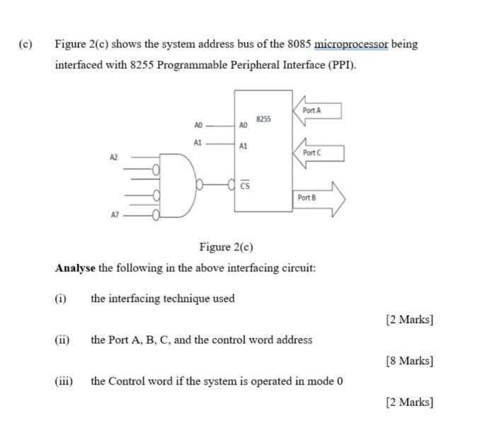
O Figure 2(c) shows the system address bus of the 8085 microprocessor being interfaced with 8255 Programmable Peripheral Interface (PPI). A2 (iii) AD A1 AD A1 12 8255 Port A Port C Port B Figure 2(c) Analyse the following in the above interfacing circuit: the interfacing technique used the Port A, B, C, and the control word address the Control word if the system is operated in mode 0 [2 marks] [8 Marks] [2 marks]
Step by Step Solution
3.43 Rating (166 Votes )
There are 3 Steps involved in it
Answer Part A The interfacing technique used here is IO interfacing techniq... View full answer

Get step-by-step solutions from verified subject matter experts