

Question: HW 0 1 MEMT 2 1 2 Last Revised 9 / 4 / 2 4 ( adapted from Hibbeler 1 0 t h ed .
HW
MEMT
Last Revised
adapted from Hibbeler ed probs. &
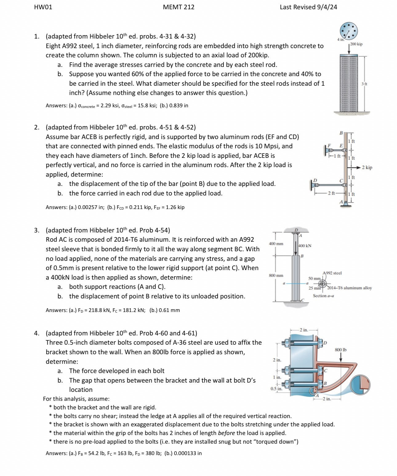
Eight A steel, inch diameter, reinforcing rods are embedded into high strength concrete to create the column shown. The column is subjected to an axial load of kip.
a Find the average stresses carried by the concrete and by each steel rod.
b Suppose you wanted of the applied force to be carried in the concrete and to be carried in the steel. What diameter should be specified for the steel rods instead of inch? Assume nothing else changes to answer this question.
Answers: aksi,ksi; b in
adapted from Hibbeler ed probs. &
Assume bar ACEB is perfectly rigid, and is supported by two aluminum rods EF and CD that are connected with pinned ends. The elastic modulus of the rods is Mpsi and they each have diameters of inch. Before the kip load is applied, bar ACEB is perfectly vertical, and no force is carried in the aluminum rods. After the kip load is applied, determine:
a the displacement of the tip of the bar point B due to the applied load.
b the force carried in each rod due to the applied load.
Answers: a in ; bkip,kip
adapted from Hibbeler ed Prob
Rod AC is composed of T aluminum. It is reinforced with an A steel sleeve that is bonded firmly to it all the way along segment With no load applied, none of the materials are carrying any stress, and a gap of mm is present relative to the lower rigid support at point C When a kN load is then applied as shown, determine:
a both support reactions A and C
b the displacement of point relative to its unloaded position.
Answers: a; b mm
adapted from Hibbeler ed Prob and
Three inch diameter bolts composed of A steel are used to affix the bracket shown to the wall. When an b force is applied as shown, determine:
a The force developed in each bolt
b The gap that opens between the bracket and the wall at bolt Ds location
For this analysis, assume:
both the bracket and the wall are rigid.
the bolts carry no shear; instead the ledge at A applies all of the required vertical reaction.
the bracket is shown with an exaggerated displacement due to the bolts stretching under the applied load.
the material within the grip of the bolts has inches of length before the load is applied.
there is no preload applied to the bolts ie they are installed snug but not "torqued down"
Answers: a; b in
Step by Step Solution
There are 3 Steps involved in it
1 Expert Approved Answer
Step: 1 Unlock

Question Has Been Solved by an Expert!
Get step-by-step solutions from verified subject matter experts
Step: 2 Unlock
Step: 3 Unlock