

Question: HW 1 0 Design a low - pass RC ( no inductors ) filter with a cut - off frequency of f _ ( c
HW
Design a lowpass RC no inductors filter with a cutoff frequency of fcHz
Remember omegapi f
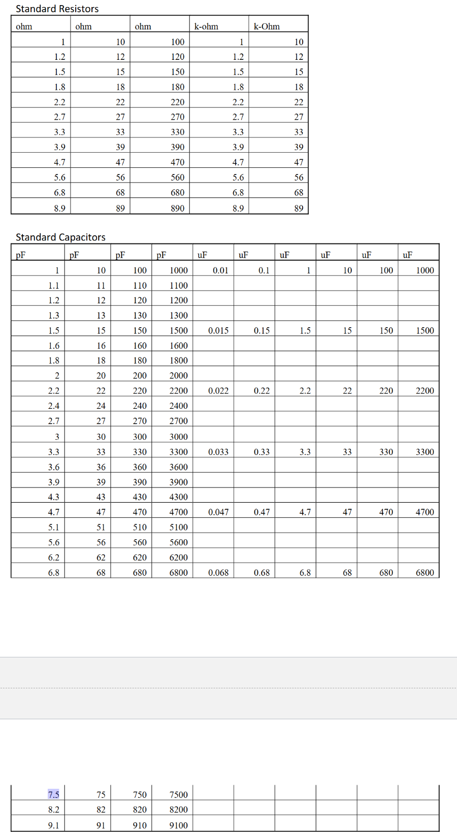
Use the tables provide for standard Resistor and Capacitor values Next Page
I recommend you choose an appropriate Capacitor then add resistors in parallel andor in
series to get the needed equivalent resistance in the appropriate part of the circuit. You should
try to get your cutoff frequency within of the specified value.
Please include your circuit drawing and how you determined the sizes of the components.
Part
For your circuit, derive the Frequency Response Gain Gvf in terms of frequency.
Provide your derivation of the frequency response function. Then use Matlab to generate the
Bode Plots. Please provide the appropriate Bode plots that cover a frequency range of Hz to
kHz
Please upload this document as a pdf Include your Matlab m file., Standard Resistors
begintabularrrrrr
hline ohm & ohm & ohm & kohm & kOhm
hline & & & &
hline & & & &
hline & & & &
hline & & & &
hline & & & &
hline & & & &
hline & & & &
hline & & & &
hline & & & &
hline & & & &
hline & & & &
hline & & & &
hline
endtabular
Standard Capacitors
begintabularcccccccccc
hline pF & pF & pF & pF & uF & uF & uF & uF & uF & uF
hline & & & & & & & & &
hline & & & & & & & & &
hline & & & & & & & & &
hline & & & & & & & & &
hline & & & & & & & & &
hline & & & & & & & & &
hline & & & & & & & & &
hline & & & & & & & & &
hline & & & & & & & & &
hline & & & & & & & & &
hline & & & & & & & & &
hline & & & & & & & & &
hline & & & & & & & & &
hline & & & & & & & & &
hline & & & & & & & & &
hline & & & & & & & & &
hline & & & & & & & & &
hline & & & & & & & & &
hline & & & & & & & & &
hline & & & & & & & & &
hline & & & & & & & & &
hline
endtabular
begintabularrrrrllllll
& & & & & & & & &
hline & & & & & & & & &
hline & & & & & & & & &
hline
endtabular
Step by Step Solution
There are 3 Steps involved in it
1 Expert Approved Answer
Step: 1 Unlock

Question Has Been Solved by an Expert!
Get step-by-step solutions from verified subject matter experts
Step: 2 Unlock
Step: 3 Unlock