

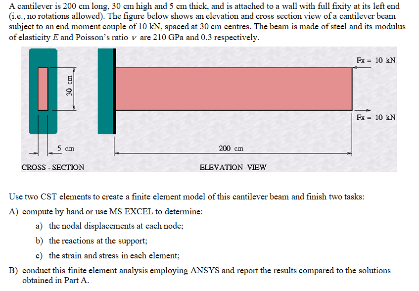
Question: ( i . e . , no rotations allowed ) . The figure below shows an elevation and cross section view of a cantilever beam
ie no rotations allowed The figure below shows an elevation and cross section view of a cantilever beam subject to an end moment couple of kN spaced at cm centres. The beam is made of steel and its modulus of elasticity E and Poisson's ratio v are GPa and respectively.
Use two CST elements to create a finite element model of this cantilever beam and finish two tasks:
A compute by hand or use MS EXCEL to determine:
a the nodal displacements at each node;
b the reactions at the support;
c the strain and stress in each element;
B conduct this finite element analysis employing ANSYS and report the results compared to the solutions obtained in Part A
Step by Step Solution
There are 3 Steps involved in it
1 Expert Approved Answer
Step: 1 Unlock

Question Has Been Solved by an Expert!
Get step-by-step solutions from verified subject matter experts
Step: 2 Unlock
Step: 3 Unlock