

Question: I nedd help with this cpu building question ASAP Problem Statement: You are to design a 4-bit mini-CPU which will perform 6 instructions: Add, XOR,
I nedd help with this cpu building question ASAP
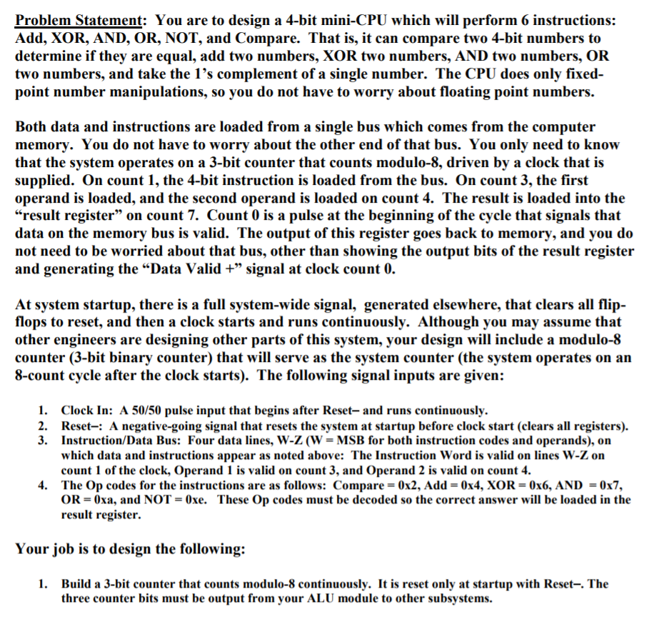
Problem Statement: You are to design a 4-bit mini-CPU which will perform 6 instructions: Add, XOR, AND, OR, NOT, and Compare. That is, it can compare two 4-bit numbers to determine if they are equal, add two numbers, XOR two numbers, AND two numbers, OR two numbers, and take the 1's complement of a single number. The CPU does only fixed- point number manipulations, so you do not have to worry about floating point numbers Both data and instructions are loaded from a single bus which comes from the computer memorv. You do not have to worry about the other end of that bus. You only need to know that the system operates on a 3-bit counter that counts modulo-8, driven by a clock that is supplied. On count 1, the 4-bit instruction is loaded from the bus. On count 3, the first operand is loaded, and the second operand is loaded on count 4. The result is loaded into the result register" on count 7. Count 0 is a pulse at the beginning of the cycle that signals that data on the memory bus is valid. The output of this register goes back to memory, and you do not need to be worried about that bus, other than showing the output bits of the result registeir and generating the Data Valid +" signal at clock count 0. At system startup, there is a full system-wide signal, generated elsewhere, that clears all flip flops to reset, and then a clock starts and runs continuously. Although you may assume that other engineers are designing other parts of this system, your design will include a modulo-8 counter (3-bit binary counter) that will serve as the system counter (the system operates on an 8-count cycle after the clock starts). The following signal inputs are given: 1. 2. 3. Clock In: A 50/50 pulse input that begins after Reset-and runs continuously. Reset-: A negative-going signal that resets the system at startup before clock start (clears all registers). Instruction/Data Bus: Four data lines, W-Z (W = MSB for both instruction codes and operands), on which data and instructions appear as noted above: The Instruction Word is valid on lines W-Z on count 1 of the clock, Operand 1 is valid on count 3, and Operand 2 is valid on count 4 The Op codes for the instructions are as follows: Compare OR = 0xa, and NOT result register. 4. 0x2, Add 0x4, XOR 0x6, AND 0x7, 0xe. These Op codes must be decoded so the correct answer will be loaded in the Your job is to design the following: 1. Build a 3-bit counter that counts modulo-8 continuously. It is reset only at startup with Reset-. The three counter bits must be output from your ALU module to other subsystems. Problem Statement: You are to design a 4-bit mini-CPU which will perform 6 instructions: Add, XOR, AND, OR, NOT, and Compare. That is, it can compare two 4-bit numbers to determine if they are equal, add two numbers, XOR two numbers, AND two numbers, OR two numbers, and take the 1's complement of a single number. The CPU does only fixed- point number manipulations, so you do not have to worry about floating point numbers Both data and instructions are loaded from a single bus which comes from the computer memorv. You do not have to worry about the other end of that bus. You only need to know that the system operates on a 3-bit counter that counts modulo-8, driven by a clock that is supplied. On count 1, the 4-bit instruction is loaded from the bus. On count 3, the first operand is loaded, and the second operand is loaded on count 4. The result is loaded into the result register" on count 7. Count 0 is a pulse at the beginning of the cycle that signals that data on the memory bus is valid. The output of this register goes back to memory, and you do not need to be worried about that bus, other than showing the output bits of the result registeir and generating the Data Valid +" signal at clock count 0. At system startup, there is a full system-wide signal, generated elsewhere, that clears all flip flops to reset, and then a clock starts and runs continuously. Although you may assume that other engineers are designing other parts of this system, your design will include a modulo-8 counter (3-bit binary counter) that will serve as the system counter (the system operates on an 8-count cycle after the clock starts). The following signal inputs are given: 1. 2. 3. Clock In: A 50/50 pulse input that begins after Reset-and runs continuously. Reset-: A negative-going signal that resets the system at startup before clock start (clears all registers). Instruction/Data Bus: Four data lines, W-Z (W = MSB for both instruction codes and operands), on which data and instructions appear as noted above: The Instruction Word is valid on lines W-Z on count 1 of the clock, Operand 1 is valid on count 3, and Operand 2 is valid on count 4 The Op codes for the instructions are as follows: Compare OR = 0xa, and NOT result register. 4. 0x2, Add 0x4, XOR 0x6, AND 0x7, 0xe. These Op codes must be decoded so the correct answer will be loaded in the Your job is to design the following: 1. Build a 3-bit counter that counts modulo-8 continuously. It is reset only at startup with Reset-. The three counter bits must be output from your ALU module to other subsystems
Step by Step Solution
There are 3 Steps involved in it

Get step-by-step solutions from verified subject matter experts