

Question: I need help with ideas for this project. What mechnism should I do ? Please give as much detail as possible.I need help with ideas
I need help with ideas for this project. What mechnism should I do Please give as much detail as possible.I need help with ideas for this project. What mechnism should I do Please give as much detail as possible.
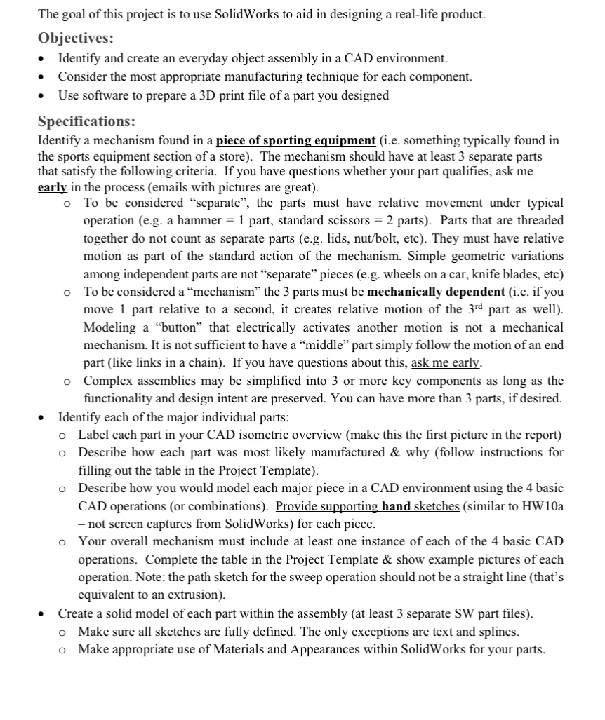
The goal of this project is to use SolidWorks to aid in designing a reallife product.
Objectives:
Identify and create an everyday object assembly in a CAD environment.
Consider the most appropriate manufacturing technique for each component.
Use software to prepare a D print file of a part you designed
Specifications:
Identify a mechanism found in a piece of sporting equipment ie something typically found in
the sports equipment section of a store The mechanism should have at least separate parts
that satisfy the following criteria. If you have questions whether your part qualifies, ask me
early in the process emails with pictures are great
To be considered "separate", the parts must have relative movement under typical
operation eg a hammer part, standard scissors parts Parts that are threaded
together do not count as separate parts eg lids, nutbolt etc They must have relative
motion as part of the standard action of the mechanism. Simple geometric variations
among independent parts are not "separate" pieces eg wheels on a car, knife blades, etc
To be considered a "mechanism" the parts must be mechanically dependent ie if you
move part relative to a second, it creates relative motion of the part as well
Modeling a "button" that electrically activates another motion is not a mechanical
mechanism. It is not sufficient to have a "middle" part simply follow the motion of an end
part like links in a chain If you have questions about this, ask me early.
Complex assemblies may be simplified into or more key components as long as the
functionality and design intent are preserved. You can have more than parts, if desired.
Identify each of the major individual parts:
Label each part in your CAD isometric overview make this the first picture in the report
Describe how each part was most likely manufactured & why follow instructions for
filling out the table in the Project Template
Describe how you would model each major piece in a CAD environment using the basic
CAD operations or combinations Provide supporting hand sketches similar to HWa
not screen captures from SolidWorks for each piece.
Your overall mechanism must include at least one instance of each of the basic CAD
operations. Complete the table in the Project Template & show example pictures of each
operation. Note: the path sketch for the sweep operation should not be a straight line thats
equivalent to an extrusion
Create a solid model of each part within the assembly at least separate SW part files
Make sure all sketches are fully defined. The only exceptions are text and splines.
Make appropriate use of Materials and Appearances within SolidWorks for your parts.
Step by Step Solution
There are 3 Steps involved in it
1 Expert Approved Answer
Step: 1 Unlock

Question Has Been Solved by an Expert!
Get step-by-step solutions from verified subject matter experts
Step: 2 Unlock
Step: 3 Unlock