

Question: I need help with sequential logic circuits and latches. I understand the basics with AND, NAND, OR, NOR, XOR, NOT gates and how they work
I need help with sequential logic circuits and latches. I understand the basics with AND, NAND, OR, NOR, XOR, NOT gates and how they work in creating truth tables. However, with the addition of sequential logic circuits and latches, I'm unable to wrap my head around the latches portion of the image (usually you need two inputs but are stuck with one before the latch). The red numbers are the correct answers. My question is, in simplest form, can you explain in brief details how the truth table came about. Also, what does R and S mean? What does previous state mean? Also, please include some drawings on some of the values in the truth table since it was very helpful in understanding the truth table for the basics of combinational circuit/logic gates.
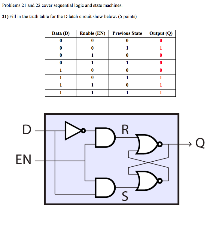
Problems 21 and 22 cover sequential logic and state machines. 21) Fill in the truth table for the D latch circuit show below. (5 points) Data (D) Enable (EN) Previous StateOutput (Q) EN DsD
Step by Step Solution
There are 3 Steps involved in it

Get step-by-step solutions from verified subject matter experts