

Question: I need help with the verilog (vivado) code using the if-else if and i need and appropriate testbench ECE 320 Lab #2 Pre-lab needs to
 I need help with the verilog (vivado) code using the if-else if and i need and appropriate testbench
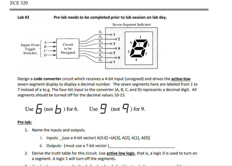
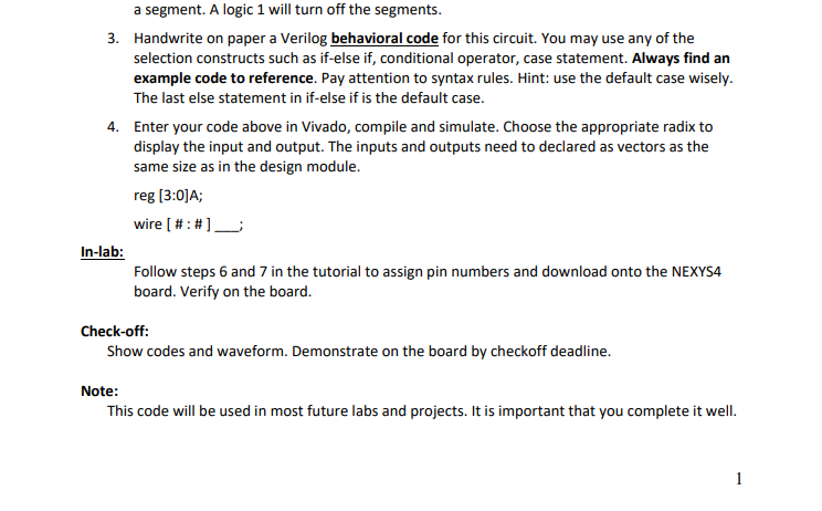
ECE 320 Lab #2 Pre-lab needs to be completed prior to lab session on lab day. Seven-Segment Indicator 0 1 02 3 Inputs From Toggle Switches B C D Circuit to be Designed X X2 X X4 X6 X2 04 5 05 06 07 Design a code converter circuit which receives a 4-bit input (unsigned) and drives the active-low seven-segment display to display a decimal number. The seven segments here are labeled from 1 to 7 instead of a to g. The four-bit input to the converter (A, B, C, and D) represents a decimal digit. All segments should be turned off for the decimal values 10-15. Use 5 (not bo ) for 6. Use 9 (not) for 9. Pre-lab: 1. Name the inputs and outputs. i. Inputs: _(use a 4-bit vector) A[3:0] ={A[3], A[2], A[1], A[O]} ii. Outputs: (must use a 7-bit vector). 2. Derive the truth table for this circuit. Use active low logic, that is, a logic O is used to turn on a segment. A logic 1 will turn off the segments. a segment. A logic 1 will turn off the segments. 3. Handwrite on paper a Verilog behavioral code for this circuit. You may use any of the selection constructs such as if-else if, conditional operator, case statement. Always find an example code to reference. Pay attention to syntax rules. Hint: use the default case wisely. The last else statement in if-else if is the default case. 4. Enter your code above in Vivado, compile and simulate. Choose the appropriate radix to display the input and output. The inputs and outputs need to declared as vectors as the same size as in the design module. reg (3:0)A; wire [ #:#]_ In-lab: Follow steps 6 and 7 in the tutorial to assign pin numbers and download onto the NEXYS4 board. Verify on the board. Check-off: Show codes and waveform. Demonstrate on the board by checkoff deadline. Note: This code will be used in most future labs and projects. It is important that you complete it well. ECE 320 Lab #2 Pre-lab needs to be completed prior to lab session on lab day. Seven-Segment Indicator 0 1 02 3 Inputs From Toggle Switches B C D Circuit to be Designed X X2 X X4 X6 X2 04 5 05 06 07 Design a code converter circuit which receives a 4-bit input (unsigned) and drives the active-low seven-segment display to display a decimal number. The seven segments here are labeled from 1 to 7 instead of a to g. The four-bit input to the converter (A, B, C, and D) represents a decimal digit. All segments should be turned off for the decimal values 10-15. Use 5 (not bo ) for 6. Use 9 (not) for 9. Pre-lab: 1. Name the inputs and outputs. i. Inputs: _(use a 4-bit vector) A[3:0] ={A[3], A[2], A[1], A[O]} ii. Outputs: (must use a 7-bit vector). 2. Derive the truth table for this circuit. Use active low logic, that is, a logic O is used to turn on a segment. A logic 1 will turn off the segments. a segment. A logic 1 will turn off the segments. 3. Handwrite on paper a Verilog behavioral code for this circuit. You may use any of the selection constructs such as if-else if, conditional operator, case statement. Always find an example code to reference. Pay attention to syntax rules. Hint: use the default case wisely. The last else statement in if-else if is the default case. 4. Enter your code above in Vivado, compile and simulate. Choose the appropriate radix to display the input and output. The inputs and outputs need to declared as vectors as the same size as in the design module. reg (3:0)A; wire [ #:#]_ In-lab: Follow steps 6 and 7 in the tutorial to assign pin numbers and download onto the NEXYS4 board. Verify on the board. Check-off: Show codes and waveform. Demonstrate on the board by checkoff deadline. Note: This code will be used in most future labs and projects. It is important that you complete it well
Step by Step Solution
There are 3 Steps involved in it

Get step-by-step solutions from verified subject matter experts