

Question: I need verification if I satisfy the question below Provide a graphical representation of your system's overall architectural framework as well as a separate functional
I need verification if I satisfy the question below
Provide a graphical representation of your system's overall architectural framework as well as a separate functional description and/or analysis of your system.This may be donevia a Functional Block Diagram, Process Flow Diagram, Sequence Diagram, or other appropriate graphical presentationfor your chosen system.
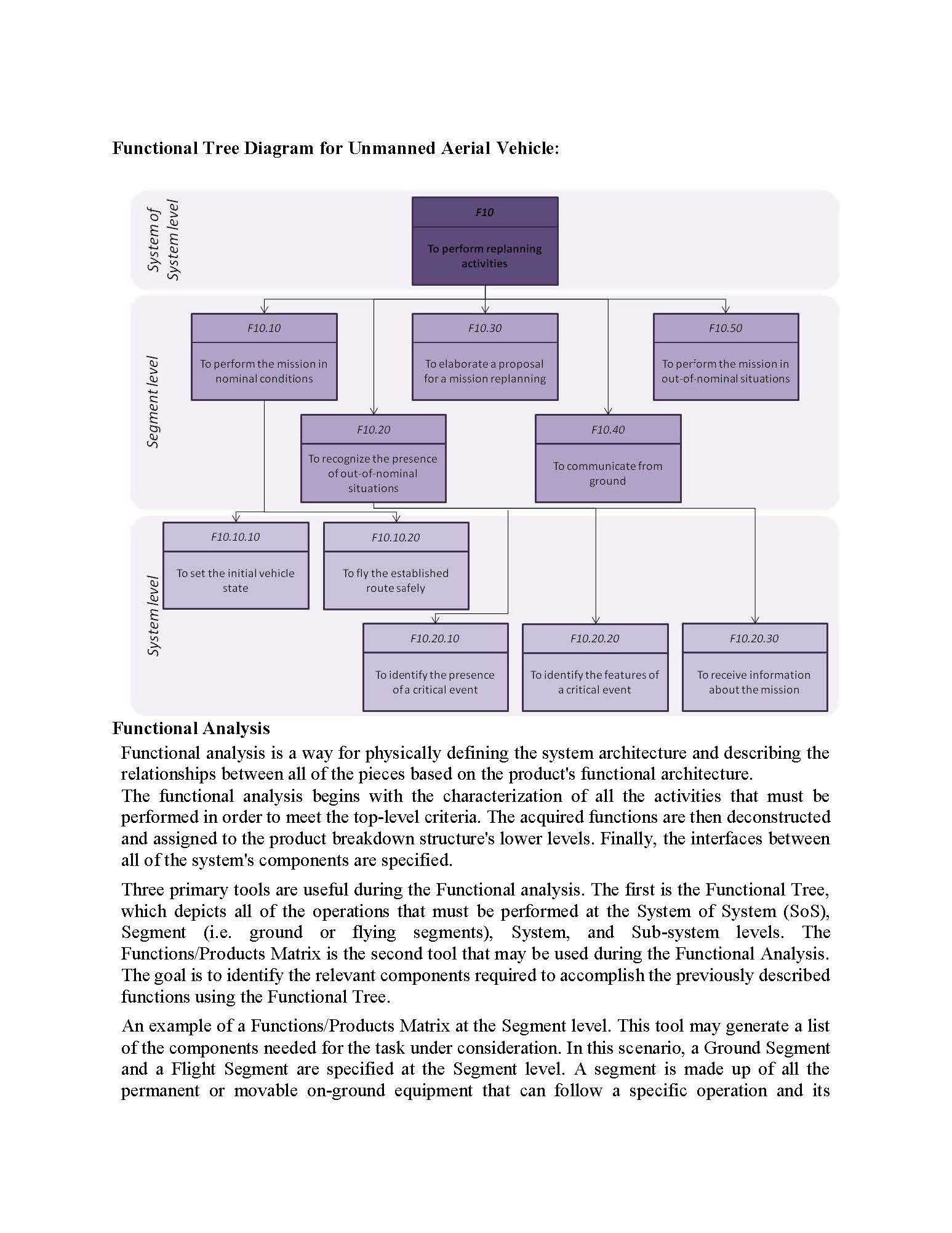
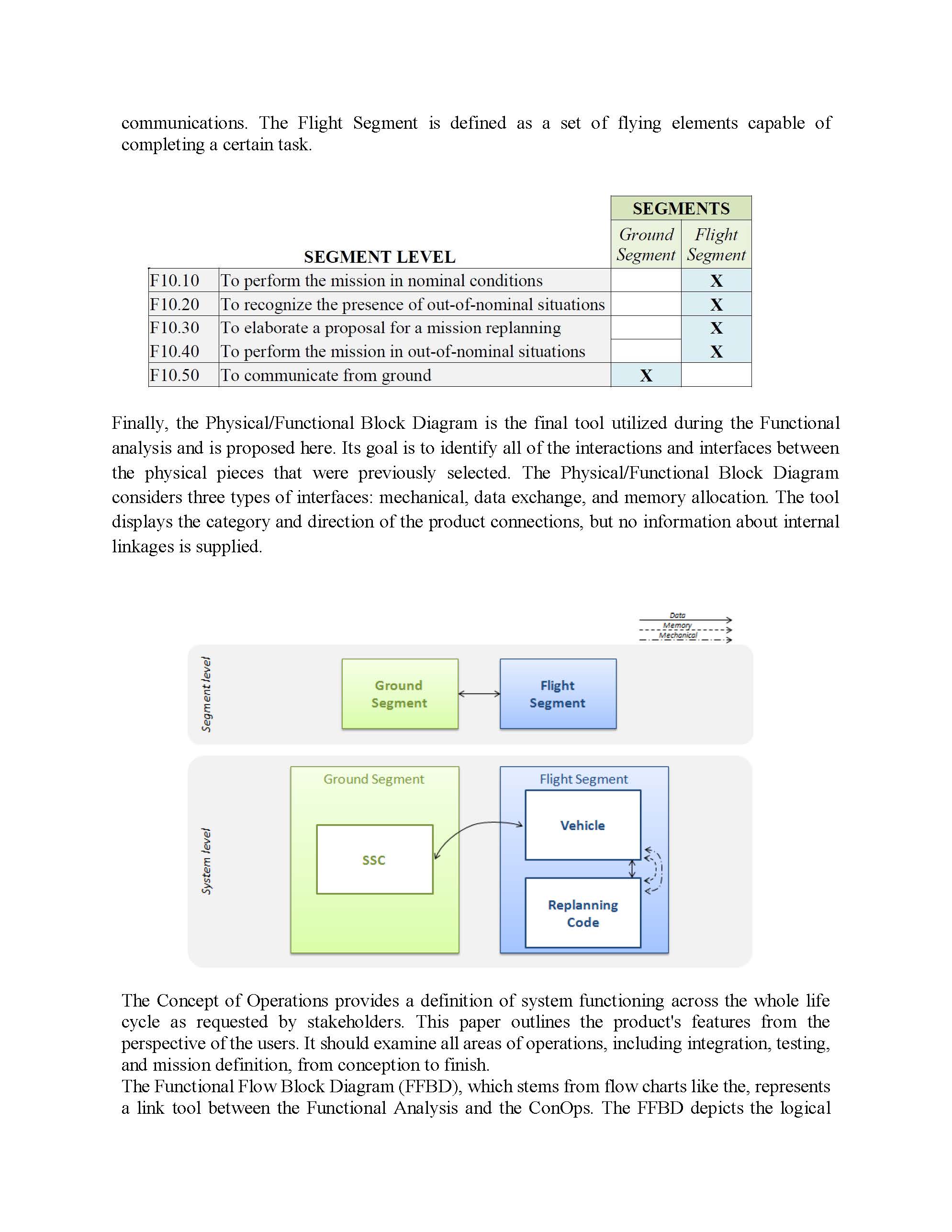
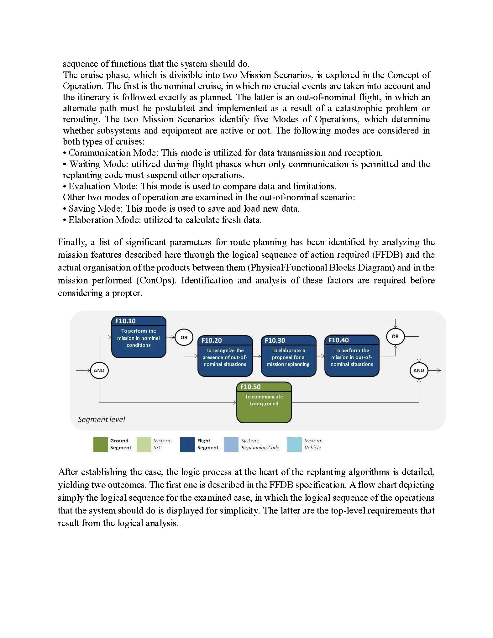
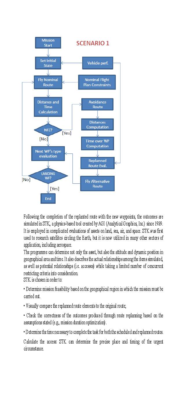

System architecture and functional Analysis approach The significant expansion in the usage of drones and UAVs has ushered in a new era of autonomous aerial vehicles in both the civilian and military sectors, with multiple benets including economic, commercial, and industrial benets, as well as low cost and energy consumption. Their use, however, led in the formation of several security, safety, and privacy problems, which manifested themselves as various cyber attacks, threats, and hurdles. The UAS Cleaning Drone is an all-electric unmanned surface vehicle (USV) that gathers marine plastic garbage in ports, canals, estuaries, and other aquatic ecosystems. Ocean Cleanup created the Cleaning Drone V1 (CDVl). It is especially useful for clearing up plastic garbage along quaysides and other areas where larger service boats cannot reach. The UAS Cleaning Drone must be modular, lightweight, and easily adaptable to multiple types of processing hardware, sensor streams, and navigation and control algorithms. A system that is compatible with UAS Cleaning Drone should also be capable of operating everything from the most basic unmanned system to the most complex unmanned system. To accomplish these objectives, the system must be a modular, Jlly threaded, event-driven programme. System architecture and functional Analysis approach The term "system architecture" refers to the parts of a system and how they are organized. These elements might be physical or mctional, and architecture can define high-level system properties such as openness or interoperability. There are numerous System architecture and lnctional Analysis approaches that can be used to design a UAS Cleaning Drone; we have chosen the Open-Standards Systems Architecture Approach for this purpose, with the selection criteria for the standards being (I) publicly available, (ii) compatibility with reliable sources, interoperability, maturity, and implement ability. OpenStandards Systems Architecture: An open architecture consists of six fundamental elements: 1. Open Standards 2. Interoperable 3. Interchangeable 4. Portable 5. modular 6. scalable OpenStandards: Parts, modules, objects, products, and systems are built using standards that are vendor- independent, non-proprietary, publicly available, and universally acknowledged. This open- standard strategy enables customers to combine hardware, software, and networks from diverse suppliers in a transparent environment to meet a variety of demands. Interoperable: The ability of systems, units, or forces to offer and accept services from other systems, units, or forces, as well as to use the services thus exchanged, in order for systems, units, or forces to work successfully together. Interchangeable: The ability of two or more components, modules, commodities, or other parts to substitute for one another transparently without requiring further hardware or software adjustments. This property provides opportunities for advancement and the introduction of new technologies. Portable: The ability to transmit and use information between two or more systems or components. The ease with which a system or component may be swapped between hardware or software environments. Modular: Physical or logical modularity to meet anctional requirements. Scalable: The ability to grow (and interlink hardware and software) to accommodate increased loads. Why OpenStandards Systems Architecture: 1. Using an open systems strategy reduces the cost and risk of owning UAS Cleaning Drone systems, delays system obsolescence, and accelerates the deployment of improved capabilities. II. .An open systems strategy reduces system costs by making it easy to implement widely used standards from a variety of vendors. We may profit from the commercial sector, where competition encourages corporations to manufacture quality items at cheaper rates. 111. Open Standards Systems Architecture provides access to alternative suppliers for the essential components and subsystems required to build UAS Cleaning Drone Systems. Because some of the required systems or components may already exist or be in development without requiring direct investment, the open systems strategy may reduce the initial investment. Furthermore, an open systems strategy avoids system obsolescence by allowing us to gradually integrate technology developments into previously established or under development systems rather than requiring substantial system redesigns or the creation of completely new systems. Functional Tree Diagram for Unmanned Aerial Vehicle: F10 System level System of To perform replanning activities F10.10 F10.30 F10.50 To perform the mission in To elaborate a proposal To perform the mission in nominal conditions for a mission replanning out of-nominal situations Segment level F10.20 F10.40 To recognize the presence of out-of-nominal To communicate from situations ground F10.10.10 F10.10.20 To set the initial vehicle To fly the established state route safely System leve F10.20.10 F10.20.20 F10.20.30 To identify the presence To identify the features of To receive information of a critical event a critical event about the mission Functional Analysis Functional analysis is a way for physically defining the system architecture and describing the relationships between all of the pieces based on the product's functional architecture. The functional analysis begins with the characterization of all the activities that must be performed in order to meet the top-level criteria. The acquired functions are then deconstructed and assigned to the product breakdown structure's lower levels. Finally, the interfaces between all of the system's components are specified. Three primary tools are useful during the Functional analysis. The first is the Functional Tree, which depicts all of the operations that must be performed at the System of System (SoS), Segment (i.e. ground or flying segments), System, and Sub-system levels. The Functions/Products Matrix is the second tool that may be used during the Functional Analysis. The goal is to identify the relevant components required to accomplish the previously described functions using the Functional Tree An example of a Functions/ Products Matrix at the Segment level. This tool may generate a list of the components needed for the task under consideration. In this scenario, a Ground Segment and a Flight Segment are specified at the Segment level. A segment is made up of all the permanent or movable on-ground equipment that can follow a specific operation and itscommunications. The Flight Segment is defined as a set of ying elements capable of completing a certain task. SEGMENTS Ground Flight SEGMENT LEVEL Segment Segment F1010 To perfonn the mission in nominal conditions X F1020 To recognize the presence ofout-ofnominal situations X F1030 To elaborate a proposal for a mission replanning X F1040 To perform the mission in out-ofnominal situations X F1050 To communicate from ground X Finally, the Physical/Functional Block Diagram is the final tool utilized during the Functional analysis and is proposed here. Its goal is to identify all of the interactions and interfaces between the physical pieces that were previously selected. The Physical/Functional Block Diagram considers three types of interfaces: mechanical, data exchange, and memory allocation. The tool displays the category and direction of the product connections, but no information about internal linkages is supplied. V: > fu 3; E E | Segment U} m U) Flight Segment '6 3- ;.V E '3 u? Replanning Code The Concept of Operations provides a defimtion of system functioning across the whole life cycle as requested by stakeholders. This paper outlines the product's features from the perspective of the users. It should examine all areas of operations, including integration, testing, and mission definition, from conception to finish. The Functional Flow Block Diagram (FFBD), which stems from ow charts like the, represents a link tool between the Functional Analysis and the ConOps. The FFBD depicts the logical sequence of functions that the system should do. The cruise phase, which is divisible into two Mission Scenarios, is explored in the Concept of Operation. The rst is the nominal cruise, in which no crucial events are taken into account and the itinerary is followed exactly as planned. The latter is an out-of-nominal ight, in which an alternate path must be postulated and implemented as a result of a catastrophic problem or rerouting. The two Mission Scenarios identify ve Modes of Operations, which determine whether subsystems and equipment are active or not. The following modes are considered in both types of cruises: 0 Communication Mode: This mode is utilized for data transmission and reception. 0 Waiting Mode: utilized during ight phases when only communication is permitted and the replanting code must suspend other operations. 0 Evaluation Mode: This mode is used to compare data and limitations. Other two modes of operation are examined in the out-ofnominal scenario: 0 Saving Mode: This mode is used to save and load new data. 0 Elaboration Mode: utilized to calculate esh data. Finally, a list of signicant parameters for route planning has been identied by analyzing the mission features described here through the logical sequence of action required (FFDB) and the actual organisation of the products between them (Physical/Functional Blocks Diagram) and in the mission performed (ConOps). Identification and analysis of these factors are required before considering a propter. F10.10 To perform the mission in nominal conditions F10.40 To perform the mission in outeofr nominal situations F1020 To recognize the presence ofouteofe nominal situations F1030 To elaborate a proposal for a mission replanning Segment level Ground System: Flight System: System: Segment 55:.\" Segment Replonnmg Cede Vehicle After establishing the case, the logic process at the heart of the replanting algorithms is detailed, yielding two outcomes. The rst one is described in the FFDB specication. A ow chart depicting simply the logical sequence for the examined case, in which the logical sequence of the operations that the system should do is displayed for simplicity. The latter are the top-level requirements that result from the logical analysis. Mission Start SCENARIO 1 Set Initial State Vehicle perf. Fly Nominal Nominal Flight Route Plan Constraints Distance and Avoidance Time Route Calculation Distances Computation NFZ? [Yes] [No] Time over WP Computation Next WP's type evaluation Replanned Route Eval. LANDING [No] WP? Fly Alternative [Yes] Route End Following the completion of the replanted route with the new waypoints, the outcomes are simulated in STK, a physics-based tool created by AGI (Analytical Graphics, Inc) since 1989. It is employed in complicated evaluations of assets on land, sea, air, and space. STK was first used to research satellites circling the Earth, but it is now utilized in many other sectors of application, including aerospace The programme can determine not only the asset, but also the attitude and dynamic position in geographical area and time. It also describes the actual relationships among the items simulated, as well as potential relationships (i.e. accesses) while taking a limited number of concurrent restricting criteria into consideration STK is chosen in order to: . Determine mission feasibility based on the geographical region in which the mission must be carried out. . Visually compare the replanned route elements to the original route; . Check the correctness of the outcomes produced through route replanning based on the assumptions stated (e.g, mission duration optimization) . . Determine the time necessary to complete the task for both the scheduled and replanned routes. Calculate the access STK can determine the precise place and timing of the urgent circumstance.Strategies for autonomous planning and replanning were presented, taking into account the specific scenario of the use of UAVs in civil applications such as territorial surveillance and emergency intervention (e.g. floods, fires). All potential criticalities were classified into four scenarios: 1) the route is diverted due to permanent or temporary No Fly Zones (NFZ); 2) the scheduled mission is modified by the ground control station; 3) a major failure forces an immediate landing (or descent to a termination point); and 4) the mission is downgraded (some waypoints are skipped) in the event of a minor fault. The research is an early design of a replanning code capable of autonomously generating new routes based on mission scenario restrictions and vehicle performance. The logical process that lies behind the code was defined using a methodology based on a Systems Engineering approach. Using this strategy, a Functional Flow Block Diagram was created to show the chronological sequence of tasks that the UAS should accomplish. Furthermore, a set of top-level conditions that the vehicle must meet in order to complete the mission was generated. Finally, he proposed technique was shown through a case study. The results were utilised to identify an alternate path, which was then simulated and confirmed using STK software. The replanning procedures presented in the study were validated by this test scenario. Future research will look at incorporating these algorithms into codes for autonomous real-time replanning, which might be used to a fleet of UAVs.References Nasa, N. A. S. A. (2007). Systems engineering handbook. National Aeronautics and Space Administration. Boggero, L., Aleina, S. C., Fusaro, R., & Viola, N. (2015). Autonomous planning and replanning of a single Unmanned Aerial Vehicle: strategies and simulations. CEAS. Rodano, M., & Giammarco, K. (2013). A formal method for evaluation of a modeled system architecture. Procedia Computer Science, 20, 210-215 Husar, R. M., & Stracener, J. (2013). Autonomous systems modeling during early architecture development. Procedia Computer Science, 20, 242-247. Luxhoj, J. T. (2013). Predictive safety analytics for complex aerospace systems. Procedia computer science, 20, 331-336. De Weck, O. L., Roos, D., & Magee, C. L. (2011). Engineering systems: Meeting human needs in a complex technological world. Mit Press. Dagli, C. H., Singh, A., DAUBY, J. P., & Wang, R. (2009, December). Smart systems architecting: computational intelligence applied to trade space exploration and system design. In Systems Research Forum (Vol. 3, No. 02, pp. 101-119). World Scientific Publishing Company. Hause, M., Bleakley, G., & Morkevicius, A. (2017). Technology update on the unified architecture framework (UAF). Insight, 20(2), 71-78. Pastor, E., Lopez, J., & Royo, P. (2006, October). A hardware/software architecture for UAV payload and mission control. In 2006 ieee/aida 25TH Digital Avionics Systems Conference (pp. 1- 8). IEEE. Cook, M. B., & Smallman, H. S. (2010). When Plans Change: Task analysis and taxonomy of 3- D situation awareness challenges of UAV replanning. PACIFIC SCIENCE AND ENGINEERING GROUP INC SAN DIEGO CA
Step by Step Solution
There are 3 Steps involved in it

Get step-by-step solutions from verified subject matter experts